Were you asking about a PSU for the NAP 140 or is yours a general question about power supplies?We thank IAN and ANDREWT , I see this as not understand so I need people to help , again
This power supply you have illustrated is unnecessarily large (500VA transformer) for the NAP140 and it has 2 sets of centre-tapped windings. Certainly you could build a dual mono amplifier (i.e. a separate PSU for each amplifier) with this arrangement but that is another topic.
Here is a link to an article on PSU design at a popular educational website:Linear Power Supply Design
Here is a link to a wiring diagram illustration in your illustrated style, of a typical PSU type used by many DIYs and manufacturers: Power Supply Wiring Guidelines
I think you will find there is plenty of information there in those articles and in the many others on that site that are associated with audio electronics 🙂
Hello again,
Well, i must admit... the amp i have build is not a "H.140 clone" anymore, i belive its original now and what the NAIM really sounds like 😀.
Have been listening to it every night from my previous post.. torching them @ high volumes @ all sorts of music.
Last mods what i did somewhere in the middle of JULY.
Also Removed the 1nF capacitor that was between input RCA shield and AMP metal case(EARTH/GROUND). From that time i have never heard any mobile dialing sound from the speakers. Before that it was still getting throught.
The RCA input shield are connected together right @ the input and then 1 wire from that point to 0V PSU GND.
AMP 0V PSU GND IS NOT CONNECTED TO EARTH!
Thats all... and for a more than a month it sounds wonderful.
I am still blown away how well MJE243 drivers perform on human voice, piano and gitarr... it is so so natural lol 😀
The point has been reached where there is nothing to do inside the case besides listening to it and building more for comparission 😉.
About the Creative SB570 soundcard i mentioned in the beginning of JULY. I recently switched from it to a integrated laptop soundcard that i was using from the very beginning. It turns out, that creative didnt had so good imaging and middle range... also this laptop sounds a lot kinda warmer too lol 😀
Well, i must admit... the amp i have build is not a "H.140 clone" anymore, i belive its original now and what the NAIM really sounds like 😀.
Have been listening to it every night from my previous post.. torching them @ high volumes @ all sorts of music.
Last mods what i did somewhere in the middle of JULY.
I finally removed all FILTER-CAPACITOR BANK series Inductors(CLCLC)...and replaced them with low value resistors:
- MAIN FILTER CRCRC (R= 50mOHM) Total: 100mR per rail i
- VBE FILTER CRCRC (R= 470mOHM) Total: 940mR per rail
- OUTPUT Inductor 1.5MM copper, 0.65uH paralleled with 8OHM resistor.
- MILLER CAP = 56pF 100V NPO directly on BJT legs.
- Still using MPSA BJT @ CSS instead of BC550
- Still using MJE24x @ Drivers instead of TIP4x
- Still using European TME warehouse 2SC5200 output transistors
- All Ultra Fast recovery diodes are replaced with standard low cost 10A Diodes and each one of them are bypassed with 10nF
- I made sure all the transformer secondary polaritys are in good order
- Finally, Twisted all the wires together - GROUND/+/- to each board
- Twisted front end wires together + and - to each board.
- Input cap now 10uF Tant, Feedback to ground cap BRASS TANT and CE bypass cap is now BC 68uF electrolytic <-- this way amp sounds bright. Adjust caps to your Taste please.
Also Removed the 1nF capacitor that was between input RCA shield and AMP metal case(EARTH/GROUND). From that time i have never heard any mobile dialing sound from the speakers. Before that it was still getting throught.
The RCA input shield are connected together right @ the input and then 1 wire from that point to 0V PSU GND.
AMP 0V PSU GND IS NOT CONNECTED TO EARTH!
Thats all... and for a more than a month it sounds wonderful.
I am still blown away how well MJE243 drivers perform on human voice, piano and gitarr... it is so so natural lol 😀
The point has been reached where there is nothing to do inside the case besides listening to it and building more for comparission 😉.
- I highly recommend using MJE24x series drivers only with SLOWER CSS BJT, for example: MPSA or low HFE BC transistors. <- Forbidding that rule will lead you in a disaster !
- Also, i would not use 500VA (rectified 41V DC) transformer in my next 2x80W amp build, too much power is lost into heat @ extreme volumes 😀
- And about the inductors in CLCLC config. I recommend to not use inductors in PSU unless you know what you are doing(impedance calculations, damping, frequency behaviour and so on).
About the Creative SB570 soundcard i mentioned in the beginning of JULY. I recently switched from it to a integrated laptop soundcard that i was using from the very beginning. It turns out, that creative didnt had so good imaging and middle range... also this laptop sounds a lot kinda warmer too lol 😀
Hi rensli
Its useful to know that you found as others here did, that the sound quality was not easily improved by incorporating more recent design ideas and components.
I guess you really are closer to Naim sound now and its been interesting looking at your experiments. That's good for DIY and others wanting to try building amplifiers based on those inexpensive kits. Nice going and thanks for sharing. 🙂
Hi Ian Finch
I forgot to say that i mounted the OUTPUT INDUCTOR right at the PCB output, again 😀.
Its not easy to do it, pcb layout and feedback traces must be modified.
That way i am sure, nothing passes throught the speaker cables into the outputs.
Yes and i also recommend not to push quiesent current too high.
Some Ebay sellers with H-140 kits, they recommend -10mV across the 0.22R emitter resistor, thats alot more then 38mA per channel for outputs... and its definitely overkill for this kits.
I set mine Toshibas 2SC5200 outputs @ ~20mA quiesent current per channel and it sounds incredible well.
Well, if you are using different Drivers and Outputs(Slower, High current) then the story changes for sure.
Finally, my case is also a naim type...i will post pics and stuff(schematic) later.
There is no HUM or strange noise from the speakers, just a clean low level WHITE NOISE.
Last edited:
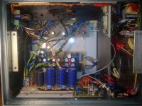
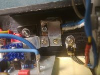
On 8 and 9 picture u can see the output inductor... its not touching the heat sink or any other metal parts anymore.
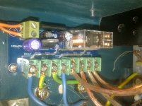
NTC that is closer to BJT is soldered directly to a copper plate 😀 And then mounted with 2 screws like all the BJT-s for better surface contact. It is mounted without any insulation and seems to sense temperature extremely well(resistance variation starts after ~ 4 second when i put a warm hand on the radiator fins).
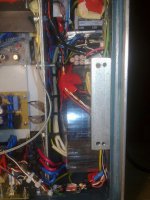
As u can see no ventilation holes in AMP section except the FAN that is sucking air throught the back of the Xformer section to cool down a 4x Xformers and LM317 regulator 😀
Schematic comes tommorow.
Rensli
- Zobel network is taken directly from emitter resistors junction point to minimize copper trace lenghts.
- Input Tant capacitor and some of the other circuit parts are under the PCB´s.
NTC that is closer to BJT is soldered directly to a copper plate 😀 And then mounted with 2 screws like all the BJT-s for better surface contact. It is mounted without any insulation and seems to sense temperature extremely well(resistance variation starts after ~ 4 second when i put a warm hand on the radiator fins).
As u can see no ventilation holes in AMP section except the FAN that is sucking air throught the back of the Xformer section to cool down a 4x Xformers and LM317 regulator 😀
Schematic comes tommorow.
Rensli
Attachments
-
 1 full.jpg925.7 KB · Views: 701
 -
 2 Filter.jpg961.9 KB · Views: 649
 -
 5 filter.jpg968.3 KB · Views: 610
 -
 8 M diode.jpg950.6 KB · Views: 609
 -
 9 VBE diode.jpg909.9 KB · Views: 595
 -
 12 DC.jpg935.2 KB · Views: 213
 -
 10 Xformer.jpg947.6 KB · Views: 196
 -
 13 right naim.jpg939.9 KB · Views: 243
 -
 14 right naim.jpg935.9 KB · Views: 217
 -
 15 NTC.jpg963.6 KB · Views: 220
Hi,
Thanks for sharing! You are one of the few who build this kit and care to share their experience. Most people disappear once their problem has been solved 🙂
I think you found experimentaly, like many, including me, that this amp doesn't need fancy tweaks. Your only deviation from the original seems to be the output inductor. Maybe later you'll remove even that 🙂 ... I did.
About the bias current, you are right there. 38ma is for the whole amp and 20mA is enough for the output transistors. This link tells all that needs to be told about relationship bias/distortion:
Naim, NAPs, Naits, distortion and bias-current settings
One little detail about the feedback that may be important... I am sorry if I repeat well known stuff...
You should take the feedback from a point that carries only the current going out to the speakers. That's the only current that must be corrected by the feedback. This means that your feedback connection must be at the very input of the inductor (in your case). This inductor must have some short single path that is not shared with any other component. Many of the kit boards are not correctly designed for that and take feedback from different common places, e.g. between the emitter resistors. Thus, the feedback introduces errors, because it takes care of stuff that never leaves towards the speakers. I hope my explanation is clear enough. This is valid for all amplifiers with feedback, and is not unique for these clones...
Regards
Last edited:
Hi Ruwe,
My pleasure, just want to make next builders/DIY-ers life easier!
Yes, if you take feedback from the right place, than you got urself better distortion numbers. Its a small fraction but still..D.Self wroted it somewhere.
This is my current setup: DC offset around ~5mV on each channel,
Enlarge for better view
Attachments

Last edited:
This is my current setup: DC offset around ~5mV on each channel,
Good stuff! ... And very small offset voltage.
Also the British design products, much better than QUAD405 NAP140.
Music fax X-ray A50 is also very good.
At least they don't have so many bugs like NAP140. The design level obviously is much better.
One thing they are the same. That is all of them are using only NPN.
Music fax X-ray A50 is also very good.
At least they don't have so many bugs like NAP140. The design level obviously is much better.
One thing they are the same. That is all of them are using only NPN.
An externally hosted image should be here but it was not working when we last tested it.
This is my small contribution to this interesting thread.
My realization is based substantially on the kit H-140 available on eBay, but with a few tweaks circuit.
These are the features and functionality that have implemented:
- Power transformer: 500VA toroidal,
- Section straightening: four double diodes high-power type UltraFast,
- Stage Filtration: 64,000 uF electrolytic capacitors with low ESR,
- Dedicated Circuit soft-start power-up,
- Circuit separate delay-time for the delayed connection and protection of the tension in "continuous" speaker,
- Two fans of thermal stabilization of fluid dynamic bearings.
It worked perfectly until the first power and despite having tried a multitude of amplifiers (PassLab, Norma Audio, Gryphon etc.) with my MAGNEPA 1.6 there is nothing that sounds more convincing, realistic and musical.
I am very happy and I recommend it without reservation.
A cordial greeting to forume and excuse me for my English translation.
I note that I had previously also made an amp based circuit NAP-140 but the final implementation, leveraging the pcb H-140 partially modified, (basically the NAP-140 of private circuit protection / current limit) returned a sound fast, detailed and capable of a dynamic markedly more pronounced.
The toroidal transformer 500 VA (dual from 30-0-30 Vac), with the drive straightening / filtering by 64,000 uF, with diode type UltraFast, delivers a dual voltage of + 41 / -41 Vdc and 8 + 8 amps which basically makes this amplifier capable of about 100-110 watts RMS per channel.
And beyond the trivial given power with both my speakers isodynamic Magnepan 1.6 that with two even more challenging THIEL CS 2.4 showed an unexpected and surprising driving capability associated with a seductive ability to return a soundstage plastic and almost tactile, almost I never experienced before with any other amplifier.
An amplifier circuit capable of a truly great musicality and an extraordinary seduction.
Last edited:
About the remarkable driving ability, precise dispensing of 8 Amps for channel is obviously under static load of 4 OHM but also much more (thanks to the energy reserve of 64,000 uF capacitors) in dynamic and on modules impedance even lower.
Last edited:
Your power supply has twice the current capacity of the original design and higher voltage rails (+/- 43V). Depending on the actual power transistors drivers and heatsinks, your output stage will be stressed driving 4 ohm or even crazy-low impedance speakers at high output. Just hope that your current limiters are adapted correctly to The SOA limits of your particular power transistors.
Magneplanars are not an easy load matter for any single pair of power transistors and using an oversized power supply, as you specify, you may expect a toasted amp soon, if you like to play loud.
If you want to drive such speakers, use a more suitable amplifier with at least 2 pairs of output transistors. Considering your speaker choices, money cannot be a problem, so why use them with the cheapest possible DIY kit?
Yes, it's true.
The Magnepan despite having a substantially resistive behavior, are not at all an easy load to any amplifier.
But not in this case using the amplification circuit is with them than with the Thiel CS 2.4, I wanted to highlight the amazing ability to drive kit H-140 if it is supported by a generous and quick power supply.
Kit H-140, unlike the original circuit NAP-140, uses as power transistors, the generous High power NPN epitaxial planar bipolar transistor 2SC5200.
As you can appreciate from S.O.A. (Acronym for the benefit of the less technical I might translate into Safe Operating Area) TOSHIBA 2SC5200 that I used and in which the asterisk * light blue (x-axis corresponds to 42VDC and ordered to 4 amps) point to the value maximum continuous regime reached into my amp for each power amplifier, with the size of the stage of power and with the choice of working voltage / power, I placed right behind the line representative of the regime of maximum Ic (current collector), but that the counter measures, on any fictional 4 ohm resistive load, it was not foreclosed the possibility, thanks to the energy reserve of 60,000 uF of elettrolici power, to achieve (and actually exceed a total suppleness with the two finals per channel), 200 watts RMS while remaining within the maximum dissipation and operation for a total of 40 amperes impulsive (total on both channels) for bursts of 20 msec.
The kit is definitely very economical in terms of cost, but can assure you that is capable of exhibiting a musicality of the highest level that few other times (especially in terms of speed, detail and soundstage) can be found in circuits that make use of more pairs of power transistors.
The Magnepan despite having a substantially resistive behavior, are not at all an easy load to any amplifier.
But not in this case using the amplification circuit is with them than with the Thiel CS 2.4, I wanted to highlight the amazing ability to drive kit H-140 if it is supported by a generous and quick power supply.
Kit H-140, unlike the original circuit NAP-140, uses as power transistors, the generous High power NPN epitaxial planar bipolar transistor 2SC5200.
An externally hosted image should be here but it was not working when we last tested it.
As you can appreciate from S.O.A. (Acronym for the benefit of the less technical I might translate into Safe Operating Area) TOSHIBA 2SC5200 that I used and in which the asterisk * light blue (x-axis corresponds to 42VDC and ordered to 4 amps) point to the value maximum continuous regime reached into my amp for each power amplifier, with the size of the stage of power and with the choice of working voltage / power, I placed right behind the line representative of the regime of maximum Ic (current collector), but that the counter measures, on any fictional 4 ohm resistive load, it was not foreclosed the possibility, thanks to the energy reserve of 60,000 uF of elettrolici power, to achieve (and actually exceed a total suppleness with the two finals per channel), 200 watts RMS while remaining within the maximum dissipation and operation for a total of 40 amperes impulsive (total on both channels) for bursts of 20 msec.
The kit is definitely very economical in terms of cost, but can assure you that is capable of exhibiting a musicality of the highest level that few other times (especially in terms of speed, detail and soundstage) can be found in circuits that make use of more pairs of power transistors.
An externally hosted image should be here but it was not working when we last tested it.
Last edited:
Given the traditional architectures that provide for each channel a couple or even a lot more transistors complementary NPN-PNP (but actually never completely identical and mirror), the circuitry NAIM to whom I am inspired, I liked very much the idea to use a pair of identical and non-complementary end, in order to minimize asymmetry of amplification.
That said, however, highlighting a fact known only to the most positions, meaning that in the complex processes of technological realization of the silicon wafers to be doped, in terms of consistency of production and final quality, is much easier to get good NPN and not PNP, here I said because my choice was right on four NPN.
And given that despite the appearance of all the various manufacturers that offer excellent active components, in the specific field of power amplifiers, Toshiba and Motorola continue to make the masters with excellent devices, my choice fell on the TOSHIBA 2SC5200, specifically designed for in high fidelity audio applications, who bought a dozen copies I to match without difficulty.
Just to name a few among the many excellent characteristics possessed, is a transistor capable of over a transition frequency of 30 MHz, a collector current of 15 amperes, a breakaway of 30 A well though, having wanted to take full advantage of the excellent qualities of "Linearity", with its bias and sizing are not gone beyond the approximately 4 amperes under "static" for each.
The adoption of two fans placed behind the heath sink me also ensured a more than adequate heat dissipation and an operating temperature that is wrong and never more than 35/40 degrees Celsius.
Last edited:
1pair of 150W devices are usually sufficient for a 60W maximum power output amplifier.
That could be a 60W into 4ohms capable amplifier, or a 60W into 3ohms, or 60W into 2ohms.
But would need to be lowered to about 50W into 8ohms due to the abominable high voltage SOA of the 2sc5200 compared to other 150W devices from Onsemi, or Sanken.
60W into 4ohms is equivalent to ~22Vpk and 5.5Apk into your 4r0 dummy test load.
Checking the SOA @ 25°C I can see that the 100ms crosses the 5.5Apk @ ~47Vce. i.e. the amplifier must not allow the Vce to exceed 47Vce when driving 5.5Apk into a reactive load while the device is at or below 25°C.
If Tc is higher during audio reproduction, then one must derate the device SOA. Look at the Toshiba note on the SOA plot.
Last edited:
Ultima Legione, those "axial" type blue capacitors, do you decouple the output stage 2SC5200's with them ?
What are the specifications for output decoupling capacitors ?
PS.
Will you try your setup with MPSA06 as CSS and MJE253/243 as drivers ?
And afterwards post your results ? 😀
What are the specifications for output decoupling capacitors ?
PS.
Will you try your setup with MPSA06 as CSS and MJE253/243 as drivers ?
And afterwards post your results ? 😀
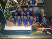
The capacitors blue of the axial type that can be seen in the photos are valid PHILIPS BC 021 1000uF 63V, in parallel to the last capacitive branch of the power supply for both the branch of positive voltage which for the branch of negative voltage.
And their presence right next to the power transistors, although it might seem trivial, ensuring immediate availability of energy unmediated parasitic inductance of the cables connected to the stage of power, brings sembre of beneficial effects on the overall musicality.
I will treasure of your information !!
Indeed it would. And you would have to reset the Cdom (Miller compensation) to ensure stability.
Note the imbalance of the LTP.
R1 passes ~0.6mA and drops ~0.6V
R2 passes ~(2mA-0.6mA) and drops ~31V
T1 operates with Vce~40V & Ic=0.6mA, Pq ~2.4mW
T2 operates with Vce~10V & Ic=1.4mA, Pq ~14mW
Hardly qualifies as a long tail PAIR !
I corrected it for you:
Note the decent balance of the LTP.
R1 passes ~0.6mA and drops ~0.6V
R2 passes ~(1mA-0.6mA) and drops ~9V
T1 operates with Vce~40V & Ic=0.6mA, Pq ~24mW
T2 operates with Vce~30V & Ic=0.4mA, Pq ~12mW
Qualifies as a long tail PAIR
Here are the measurements from one channel of my NCC200:
Note the excellent balance of the LTP.
R1 drops 0.499V therefore passes 0.499mA
R2 drops 10.78V and therefore passes 0.49mA
T1 operates with Vce~40V & Ic=0.5mA, Pq ~20mW
T2 operates with Vce~30V & Ic=0.5mA, Pq ~15mW
Definitely qualifies as a long tail PAIR even if we include the negligable effect of the VAS transistor base current.
Useful and valuable contribution of experience.
And in any case, to those approaching or it is considering this particular amplification circuit, beyond numbers and measurements, confirm that the absolute excellence and realism of reproduction of which, this seemingly normal audio kit is capable, especially if added to audio setup made of audio sources, preamplifier and speaker of large claims and value.
And in any case, to those approaching or it is considering this particular amplification circuit, beyond numbers and measurements, confirm that the absolute excellence and realism of reproduction of which, this seemingly normal audio kit is capable, especially if added to audio setup made of audio sources, preamplifier and speaker of large claims and value.
Last edited:
- Home
- Amplifiers
- Solid State
- NAP-140 Clone Amp Kit on eBay