Some transformers particularly large EI and many toroids do not tolerate impure sinewave as a mains feed.
If there is asymmetrical AC waveform, the core reads this and the core adopts a flux as if it were being fed an AC with a DC error superimposed.
That DC error makes the core saturate and drops the inductance presented to the input waveform. This leads to the primary current increasing enormously. This heats the primary winding and makes the transformer "growl".
The solution is often to place a DC blocking capacitor in the primary winding circuit. The capacitor needs to be very high capacitance and when assembled correctly can be of quite low voltage rating. BUT there are many schematics on the web that are wrong.
Some dedicated Threads on this Forum.
Peranders sells a PCB for this.
Last edited:
This isn't a good move IMHO. TR4/6 make up the voltage amplifier and its ~ 6 mA current source which requires high and linear gain across the full bandwidth whilst swinging virtually +rail to -rail voltage. That requires low Cob (base-collector capacitance) and there are not many transistors that can handle this duty with low capacitance or rather, that particular design capacitance ...... I notice that TR4 and TR6 seem to run hot, not sure if that is ideal or beneficial for long life, they say 2SB647 and 2SD667 on them if that is to be believed. I have 2SC5171/2SA1930 I could sub for them, they are TO220 so I could also fit small sinks. Good move? I think I have some ZTX/653/753 at home but I'm about 5 weeks away from another visit and there's nothing at all available here in the desert....
My experience with these various clones and the original product are that the sound quality is largely dictated by the purposely off-balanced input pair TR1,2 and the VAS, TR4/6. Pay attention to these arrangements as designed and you get the best compromise of sound. You could also build this as a straightforward amplifier but those I've heard modified this way tend to be lacklustre and there are much better designs for messing about with.
Other transistors like the drivers you suggested may 'work', but not ideally. Since the Cob capacitance is a part of the frequency compensation capacitance, high frequency gain and stability are dependent upon the choice of TR4 so one needs to be particular about it. With C4=39 pF, ZTX653/753 with Cob 30pF, are still best match. 47pF usually sounds better with 2SD667/B647, depending on the source, which with Ebay kit sellers and their dodgy parts, is never certain. Otherwise, leave the supplied parts as is until you get you have the original types, if you want to try them out.
Yes, even the larger case 2SD667/B647 will run hot - ZTX types will be hotter still but they can handle it as long as the heat is not due to instability or assembly errors. Mine don't reach 60C, which is still OK but obviously depends on ambient temperature.
Interesting points.
Is the schematic you posted the schematic of a Naim amplifier, or just another clone?
I'm interested that you comment the sound quality is largely dictated by the unbalanced input pair and the VAS.
The input pair unbalance is seen in my boards as with the schematic you posted. so hopefully even with different devices BC546B as opposed to BC239C much of this remains. So far as the VAS is concerned I've tabulated the fT and Cob of the 6 devices in the picture. Maybe these are not the only parameters that affect this position but so far as these parameters go the 5171/1930 do not seem so far from the 667A/647A.
I don't see an order of magnitude difference here. Maybe it's more subtle.
Is the schematic you posted the schematic of a Naim amplifier, or just another clone?
I'm interested that you comment the sound quality is largely dictated by the unbalanced input pair and the VAS.
The input pair unbalance is seen in my boards as with the schematic you posted. so hopefully even with different devices BC546B as opposed to BC239C much of this remains. So far as the VAS is concerned I've tabulated the fT and Cob of the 6 devices in the picture. Maybe these are not the only parameters that affect this position but so far as these parameters go the 5171/1930 do not seem so far from the 667A/647A.
An externally hosted image should be here but it was not working when we last tested it.
I don't see an order of magnitude difference here. Maybe it's more subtle.
and yet a highly recommended VAS transistor is the 2sa1360.
Cob typically 2.5pF @ 10Vce, the NPN is even lower @ 1.8pF.
But this is a 5W, 50mA device.
Cob typically 2.5pF @ 10Vce, the NPN is even lower @ 1.8pF.
But this is a 5W, 50mA device.
and yet a highly recommended VAS transistor is the 2sa1360.
Cob typically 2.5pF @ 10Vce, the NPN is even lower @ 1.8pF.
But this is a 5W, 50mA device.
So way lower than the ZTX devices! Wouldn't that "change" the character again?
Indeed it would. And you would have to reset the Cdom (Miller compensation) to ensure stability.
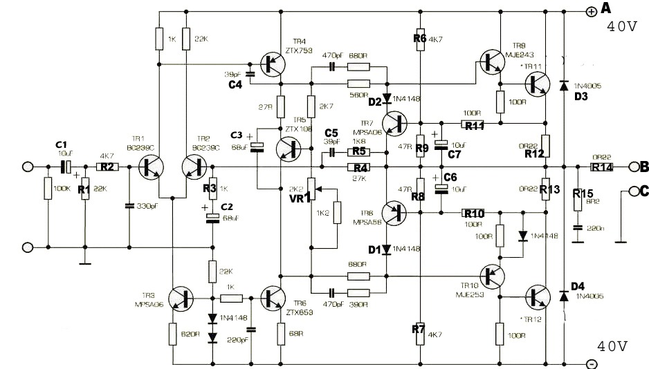
Note the imbalance of the LTP.
R1 passes ~0.6mA and drops ~0.6V
R2 passes ~(2mA-0.6mA) and drops ~31V
T1 operates with Vce~40V & Ic=0.6mA, Pq ~2.4mW
T2 operates with Vce~10V & Ic=1.4mA, Pq ~14mW
Hardly qualifies as a long tail PAIR !
Note the imbalance of the LTP.
R1 passes ~0.6mA and drops ~0.6V
R2 passes ~(2mA-0.6mA) and drops ~31V
T1 operates with Vce~40V & Ic=0.6mA, Pq ~2.4mW
T2 operates with Vce~10V & Ic=1.4mA, Pq ~14mW
Hardly qualifies as a long tail PAIR !
If you read through the thread, you'll see much the same schematic, and similar comments about the older and unusual components, circuit tweaks etc. recurring as new builders post here. The design harks from the 1970's and used components that were considered top-notch then. The above circuit diagram is the Generic Naim Schematic which once applied to all models, with minor variations, bridging etc. It's been retouched here and there, since the original scanned poorly. (See Acoustica.org website)
Despite the fact that the design is tweaked and far from technically correct, as AndrewT's numbers show, it does benefit from better input stage transistors than BC546/56. BC550C/60C are close to original types and will prove lower noise and probably easier to reduce offset if necessary. All the wonder parts in creation won't save a noisy input stage, which seems to escape the attention of many who instead, waste heaps on very low noise resistors. Note that the Japanese part number transistors have different pinouts to Euro (pro-electron) types - a deterrent to swapping the small parts willy-nilly.
Apart from not needing oversize parts to make them to run cooler, trying to squeeze TO220 parts with different pinouts into the TO92 size footprint is surely a bad idea. If you are using high rail voltages because of opting for 30VAC transformer windings, you will probably have troubles with other parts of the circuit too. 43-45VDC rails are too high if you use the original design. You can certainly substitute higher voltage parts and add heatsinks but the final result may not be what you were hoping to hear, as said earlier. The ZTX series parts offer the better sound (even the commercial clone NCC200 by Avondale Audio retains them) but you can get the supplied parts to work almost as well by judicious (you may need a 'scope to see any oscillation problems) adjustment of the compensation cap.
Otherwise, Ft and Cob are 2 sides of the same coin. There are other issues like gain linearity, early voltage and so on to consider for VAS performance too. I don't mean technically best performance - just appropriate to the task of sounding something like the original. You may not be looking for original sound but I suggest the options aren't actually very good. I've tried a lot of variations on the Naim and have never been satisfied, always concluding that it would have been better to start with a simpler, clean sounding conventional design.
BTW, TR4/6 parts supplied with the kit are not genuine. Hitachi pulled out of making semis when they joined with NEC to form Renesas many years ago, so the "Hitachi" logo mark on larger 2SD669/B649, is a look-alike fake and there are buckets of both pair types available cheap on Ebay. I've measured Ccb (Cob is calculated) varying between 12pF and 32pF over a few years, so don't put any faith in datasheets without real measurements there. It will get quite confusing if you start out by redesigning with bad info.
Thanks Ian,
I've read through pretty much all the thread over a few days though its all become a bit of a soup of course. I've certainly seen a fair few slightly different schematics during that time but if the one you posted is as close to the factory version as known that would seem a good place to start. I probably have most of the semiconductors on hand from NOS parts back at home. Certainly have some 653/753 and I think some BC239 as well. I have no issue with pin outs, spent years swapping stuff to suit what's on hand. I don't know what the TR4/6 supplied are, they surely are not genuine and from what you say about the varying capacitance perhaps this would also need judicious selection.
I'm not real happy with 43v either. To retain the existing trafo I'll perhaps buck it a bit.
As to expectations, well I'm not really sure, or overly concerned. It's just fun by and of itself. Now if there were a particular idea in mind it would in due course be to recreate as close as practicable a real Naim amplifier, without actually shopping for one at 500 quid! There might be "improvements" but as you said, this isn't the place to start really if you just want a good amplifier, there are better alternatives.
Martin
Well it's wired, it's working, and it sounds very nice. I only have a pair of Tannoy 6o3's on some home made stands but there seems no real comparison with the simple 2n3055 amp that it replaced. I don't have it here to compare but I would say it sounds every bit as good as my Cyrus 1 at home, similar detail and clarity at least but seems to have more low end than I recall the Mission has. I'm impressed and if improvements are as possible as it would seem are suggested then it's going to be a lot of fun. My source material here is limited, just 24 bit 96kHz FLAC files through the line out from my Mac Book.
Next step will be to build the second one together with the other little bits n pieces for bi-amping. After that I plan to upgrade the speakers, probably to IPL TL's.
So far, this is a lot of fun 🙂
Martin
Next step will be to build the second one together with the other little bits n pieces for bi-amping. After that I plan to upgrade the speakers, probably to IPL TL's.
So far, this is a lot of fun 🙂
Martin
It would be interesting to know how 2N3055 would sound in a Naim clone. I have some cheap 3055 ( 30 cents US each and rugged ). I suspect they do not have real 3055 inside. The MJ15015 is a very interesting version. I don't know if the 2N3055 they sell are fallout voltage spec ? Seems they might be as they are on the same spec sheet. TIP3055 was said to be a better version where T03 can not be used, in it's day the TIP was better . used in A&R A60 . Some say the slower devices sound nicer, I say it if asking who "some" are ? The BDY56 Naim used in the early days was 10 MHz. That was best of type in it's day. Now it is medium fast.
MJ15015G - ON SEMICONDUCTOR - Bipolar (BJT) Single Transistor, AUDIO, NPN, 120 V, 6 MHz, 180 W, 15 A, 70 | CPC UK
MJ15015G - ON SEMICONDUCTOR - Bipolar (BJT) Single Transistor, AUDIO, NPN, 120 V, 6 MHz, 180 W, 15 A, 70 | CPC UK
Yes, a high voltage variant of the 3055.
I have a bag of 3055's at home with various labels on them and they are freely available in town. Fake or not the choice is usually offered at point of sale, they will say China or original, price difference is typically 2 to 3 times. How much difference? I've not really checked.
The 2N5886 looks a suitable candidate also though slightly lower Vceo.
80V, 4MHz(min), 200W, 25A cont, 50A peak! Also at Farnell in UK
That looks excellent. The 2N3055 I have are from India. The more I use them for PSU projects the more I suspect they are OK. I am tempted to make the Gogny amp from 1964 with them . It is 50 watts into 1 ohm for a ribbon mid range/ tweeter panel. It uses a 2N3055 to drive a 2N3055. That is reasonable as the gain of the 3055 is 5 at that load. On a light load I measured a gain of 40 with these. In free air a T03 is 2 watts. For that alone I am happy with my 30 cents US devices. Often it is enough.
CPC I listed is very often cheaper than parent group Farnell. If you try the MJ150115 I think the parent is much more expensive. That is a nice device. I bought 20 for a big Quad 303 clone that might get to build one day.
CPC I listed is very often cheaper than parent group Farnell. If you try the MJ150115 I think the parent is much more expensive. That is a nice device. I bought 20 for a big Quad 303 clone that might get to build one day.
Ahh.....that's what we like to hear. Nice going 🙂Well it's wired, it's working, and it sounds very nice........So far, this is a lot of fun 🙂.....
This thread has been running almost 8 years. Quite impressive. I wonder if in that time there are any that have bought the kits, built them and continue to use them. I'm sure the very nature of this sort of thing, and indeed this forum would suggest that most if not all have been modded, changed, upgraded or altered in some way. It would be interesting to know what sort of failure rates might be attributable to these fake transistors.
Lol! 😀 - many people using kits as the basis of an amp are just interested in having something - anything that works! Good sound quality is a bonus if the mods and "upgrades" don't kill it off first. 🙄
In my experience with several local kitbashers, most basic amplifier builds are consigned to storage after the initial interest wears off because they are either left unfinished, inconvenient to use or just don't prove to sound as good as first impressions suggested. Inexperienced modding based on tinkering with sound effects simply by ear, often results in poor overall qualitative performance too.
I doubt fake parts like output transistors get much opportunity to fail by exceeding SOA limits because people with audiophile aspirations don't usually need high power (1-5W demand is realistic). Semiconductor fakes supplied in kits are usually just poor copies or relabelled parts that work OK as substitutes but not optimally and, from some suppliers in the past, even wrong pinouts! If one were to do something about this, sourcing genuine original parts or better substitutes where necessary, would be a good investment, IMHO.
There is one type of tinkering that should work. Larger transformers and larger capacitors. I prefer 22 000 uF x 2 with earthing as recomended in Douglas Self's book. The screw terminal ones usually are a little better. Near the power transistors decoupling caps can be as high as 2200 uF. A 500VA transformer is about right. BBH Aerovox would be a typical Naim part sold through CPC Farnell. Tiger transformers of Peterborough even wound a Naim style transformer for a reasonable price for a friend . Same black tape.
When I was 16 the lab technician at college taught me how to test transistors. Base to emitter , base to collector reads as a diode. So simple and yet some probably don't do this test. There can be a real diode in reverse bias collector to emitter. Not a bad thing if so. I had a very strange fault on a Rotel amp ( RA 840 mK 1 ). It was a rejected trade in. It worked the headphones fine with no power transistors. Thus the drivers were OK ( Rotels are tough ). All the transistors measured fine until I measured collector to emitter. It was short circuited. Now that fooled me as I hadn't considered the be,bc junctions would measure 0K if a ce short. It's now my sons amp and a very good one. Designed by Stan Curtise who was in the same group of designers as Alan Mornington West who most likely designed the Naim amps.
When I was 16 the lab technician at college taught me how to test transistors. Base to emitter , base to collector reads as a diode. So simple and yet some probably don't do this test. There can be a real diode in reverse bias collector to emitter. Not a bad thing if so. I had a very strange fault on a Rotel amp ( RA 840 mK 1 ). It was a rejected trade in. It worked the headphones fine with no power transistors. Thus the drivers were OK ( Rotels are tough ). All the transistors measured fine until I measured collector to emitter. It was short circuited. Now that fooled me as I hadn't considered the be,bc junctions would measure 0K if a ce short. It's now my sons amp and a very good one. Designed by Stan Curtise who was in the same group of designers as Alan Mornington West who most likely designed the Naim amps.
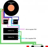
I have a little question about the Nap140 power supply does it take 2 secondary windings to obtain 40-0-40 V DC output voltage
dual bridge rectifiers require a dual secondary transformer.
single bridge rectifier can use either a dual secondary transformer, or a centre tapped transformer.
single bridge rectifier can use either a dual secondary transformer, or a centre tapped transformer.
Note that separate transformer windings must be connected "in phase" (shown by the solid dots) to get any usable AC output for use with a single bridge rectifier. Everything else about dual secondary windings connected in series, will effectively be the same as one tapped secondary winding.
- Home
- Amplifiers
- Solid State
- NAP-140 Clone Amp Kit on eBay