'Good to hear of your success, c3kkos 🙂
Hi George. It's likely that a number of small semis may actually be rated too low for nominal +/- 50V rails, including the critical ZTX types for the VAS (voltage amplifier stage), assuming those were the types supplied. Perhaps not, considering the other substitutes but I don't know much more about your kit than you have told us. The substitute power transistors you mention are well within ratings and should be fine once the bias is set correctly. Having said that, bias currents in the input and VAS stages will be somewhat higher and will need trimming with different series resistors in any event.
The general solution to power problems is to do what anyone building amplifiers for themselves should do before powering up - make a Dim Bulb Tester (DBT) from suitable, safe electrical light fittings, an insulated box and a spare power lead. Fit it between the mains outlet and your amp to test whether it is assembled right and doesn't catch fire. Measure the supply DC voltages which should be normal + about 25% if the bulb stays dim but lower, if bright. The bulb automatically reduces the supply voltage to the transformer and thus the DC rail voltages, protecting the amplifier as long as it is drawing some current, with its high, hot resistance.
Google the tester title - there are dozens of good and even not so smart ways to make up a low power tester with a 60-100W incandescent (halogen or plain old tungsten wire type) lightbulb. Don't try LED, compact fluorescent or other types of lightbulb. They don't work for this purpose.
So, the amplifier may work OK for some period after first power up but seriously, never power amplifiers at higher supply voltages than specified + perhaps 8%, which should also cover a worst-case variation of your AC line voltage. My local supply is generally a steady 246 VAC but in recent times, solar powered, grid feeding installations occasionally make that worse. YMMV
Options:
Reduce the mains input using a variac.
Change the Sony psu’s transformer.
Regulate the rails down.
Redesign the circuit.
Reduce the mains input using a variac.
Change the Sony psu’s transformer.
Regulate the rails down.
Redesign the circuit.
Hi All
Thanks to Ian and Traderbam for your responses and advice.
one of the problems around her is getting new decent size transfomers at a reasonable price , nece the trying to use / repurpose older ones.
The DBT is in my kits of bits somewher so that would get used in any case - but a good reminder to all.
I'm not keen on swapping out semi's just yet sn I think the best option may be to wait till i find an appropriately sized transformer .
The usage of the regulated power supply is also an option..
Traderbam I Cant afford / justify variac - The sony transformer change i alluded to above .
Regulation......how about this for an idea...
Regulate the front end to a lower voltage / low amperage - (easy) but leave the output transisitors at 50V--- believe that running front end and outputs at a differnt voltage is sometimes done -- not sure in this case ..
My ambitions far exceed my knowledge.
this is only a play project out of some interest (and for a secondary system)- i still have another Aleph 5 to complete (already built 1 ages ago) amongst other projects...🙂
I wonder how reliable (correct/non fake semis) are the LJM boards...?
Many thanks
Rest assured, splitting the front end from the output stage by using separate supplies will not make for good Naim quality sound. It may still sound fine for an average amplifier but we usually buy particular types of kits in the hope of hearing something of the original product's sound quality which made them special and worth the asking price. That's not saying you can easily match the original sound but getting closer at little cost should be well worthwhile.
You could also settle for lower voltage, i.e. 25-0 + 25-0 VAC transformer that would give you 35VDC rails. Consider that NAP 140 uses those rail voltages and is quite comfortable putting out 70W per channel to 4 ohm loads with them. It doesn't have all identical resistor values to the well known NAP 250 schematic, since there need to be small adjustments to the current limiting resistor values in the VAS stage to keep the bias current there up at a consistent 12 mA and the collector resistor of the input side LTP transistor is a little smaller too, for a related reason in the input stage.
Re LJM boards, I've read some comments from him that even his boards and logos are being copied - 'have been for years but his new graphics might be a bit tougher to copy. All the same, I think other kitsellers are selling their kits against his with his PCBs or maybe excellent copies of them. Either way, it hurts his business but you can buy his current kits directly from him at Ali Expess or Tao Bao, I think. I recently bought his little SMT+thru hole board "Preamp 9" and it's quite good regardless of the low cost. I've bought his L12-2 kits and no fake Sankens there but be suspicious of any MT200 size Sankens on offer from others.
Last edited:
Thanks Ian for your words of wisdom.
whilst i would ideally like the 40v rails - 35v i can supply - splitting off from my Aleph 5 supply.
Was hoping to have amps in stand alone cases but in the time i seek out an appropriate transformer - i can redirect power from my Aleph- at least in the interests of getting it going.
That transformer is supposed to be 50V Ct @50A- and does in deed supply 35v+/-
In further reading i note issues with orientation of Q1 Q2 and the suggestion to move q5 to the heatsink ( even replacing with one of the TIP types )
I wonder if this would allow use of a ventilated case as opposed to a sealed one....?
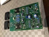
If intersted i attach a photo of the pcb i have (2 off)
Cheers
whilst i would ideally like the 40v rails - 35v i can supply - splitting off from my Aleph 5 supply.
Was hoping to have amps in stand alone cases but in the time i seek out an appropriate transformer - i can redirect power from my Aleph- at least in the interests of getting it going.
That transformer is supposed to be 50V Ct @50A- and does in deed supply 35v+/-
In further reading i note issues with orientation of Q1 Q2 and the suggestion to move q5 to the heatsink ( even replacing with one of the TIP types )
I wonder if this would allow use of a ventilated case as opposed to a sealed one....?
If intersted i attach a photo of the pcb i have (2 off)
Cheers
Attachments
Don't move Q5 (assuming that's the Vbe multiplier transistor) to the heatsink. That's the traditional strategy for bias control of a standard Emitter Follower (EF) design output stage. The Naim amplifier though, is a quasi-complementary design. Note that the power transistors are all the same, NPN only types. Consequently the bias current is much lower than EF designs and remains a compromise of 2 very different thermal coefficients.
To ensure the amp is safe and reliable, the air temperature inside the closed case of the amplifier has proven to be a good reference but later Naim models, e.g. NAP200 (the real thing, not the very cheap, simplified Ebay variety) now fit the Vbe multiplier transistors on the underside of the PCB, close to the bottom of the case, to speed up the settling of the bias.
The case of NAP and NAIT models is the heatsink and that means using all-aluminium cases, not steel, so it isn't as silly as it seems and this method has a considerably quicker settling time. Previously it took up to 30 mins to get decent sound from the amplifiers, as the air inside slowly warmed up.
Member
Joined 2009
Paid Member
It’s a bit of a kludge if you ask me. In my clone I fixed it with a design change to the Vbe multiplier.
Afterthought: I don't know whether a Sydney manufacturer is close enough for you but Tortech Transformers there have a special on stock 300VA 25+25V transformers @ $87 inc. GST + a low ordinary postage charge. That's far cheaper and better quality than the usual retailers' Chinese imports. Professional people to deal with too, as I recently found. On-line, Paypal etc. all there, easy.
I don’t see a problem with running the Darlingtons at 50V and the rest at a lower voltage. I don’t think that would affect the Naim sound. If the regulation isn’t implemented carefully it will.
The Naim Vbe multiplier is thoughtfully designed even if it doesn’t seem so at first. It’s typically Naim.
Its obvious role is to prevent thermal runaway and to stop the power transistor bias dropping too low.
The boxes were Al for heatsinking and to avoid the undesirable electro-magnetic properties of ferrous metal.
Its obvious role is to prevent thermal runaway and to stop the power transistor bias dropping too low.
The boxes were Al for heatsinking and to avoid the undesirable electro-magnetic properties of ferrous metal.
What sort of regulation for the front end? Active regulation is tricky to get right and not necessary.
I would choose a simple, resistor + zener + cap. regulator.
Each channel should have its own regulation taken off the +/-50V rails. So you will need 4 of each part.
The amp. front-end, average current draw is some 12mA. To drop 10V (from 50V to 40V) requires about 800 ohms. Go for 470 to allow plenty of idle current through the 40V zeners.
The resistor idle current = 10/470 = 21mA. The average resistor power dissipation will be 21mA x 21mA x 470 = 0.2W. Choose 0.5W resistors.
The zener idle current = 21mA - 12mA = 9mA. Average dissipation will be 9mA x 40 = 0.4W. Choose at least 1W zeners...preferably higher and give them air space.
Use a single, big cap across each zener. At least 4700uF.
I'd want to compare the result of that zener regulation with the standard NAP140 design before committing to it. I have done similar for myself and a pal quite some years ago and concluded that I preferred the sound of the original, straight-through power rails, by a fair margin.
There was a difference and when regulated to a lower voltage, it was indeed a cleaner or maybe leaner sound but lacking some of the Naim character. If you weren't fussy about that sound quality and just wanted a clear sounding amp. based on a Chinese kit, then sure, but regulate the front end of one that comes unassembled. From the pic, I think this one is a NAP140 clone, ready assembled but you can still strip off some parts and cut the relevant copper tracks to squeeze at least some of the extra parts onboard if you want to try the +/- 50V power supply anyway.
There was a difference and when regulated to a lower voltage, it was indeed a cleaner or maybe leaner sound but lacking some of the Naim character. If you weren't fussy about that sound quality and just wanted a clear sounding amp. based on a Chinese kit, then sure, but regulate the front end of one that comes unassembled. From the pic, I think this one is a NAP140 clone, ready assembled but you can still strip off some parts and cut the relevant copper tracks to squeeze at least some of the extra parts onboard if you want to try the +/- 50V power supply anyway.
Last edited:
Thanks Guys for your commetns .
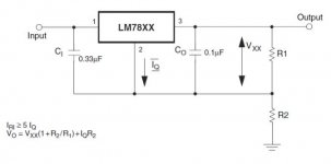
I wonder if instead of front end regulation using resisto/ cap / regulator , we add a 7824 / 7924 regulator into the mix (+ 16v zener to get to 40v ) might this give a better result?
I tried this approach on an old hafler dh-200 with very favourable results...
I wonder if instead of front end regulation using resisto/ cap / regulator , we add a 7824 / 7924 regulator into the mix (+ 16v zener to get to 40v ) might this give a better result?
I tried this approach on an old hafler dh-200 with very favourable results...
I reckon you want either a zener or a regulator, not both. Sort of the worst of both worlds if they are in series. Keep it simple. 🙂
If you use a regulator it will need >50V Vi-Vo rating, like an LM317HV. You'll also need an extra pair of smoothing caps. This could get expensive. So I'd stick to the zener regulator on the front-end in the first instance.
The thing is, to make something of audiophile quality you'll have to go to a lot of trouble and expense. A lot more than a new transformer or variac. I'm just saying.
That’s what I thought you meant. The regulator adds no value. In fact, it makes things worse. I say, just use a resistor, a zener and a capacitor. Simple, low cost, reliable.
Thanks Traderbam
I have much to learn.....my background is not electronics- and the theory I understand does not extend much past High School physics and reading a bit.
Nonetheless , I have completed a few projects - while standing on the shoulders of others...🙂
Cheers
I have much to learn.....my background is not electronics- and the theory I understand does not extend much past High School physics and reading a bit.
Nonetheless , I have completed a few projects - while standing on the shoulders of others...🙂
Cheers
Hey George,
We all have plenty left to learn. You may get overwhelmed in here with a variety of opinions and theories and experience. My advice is to keep it simple, build up your skills in baby steps. And keep experimenting.
In this Naim thread you’ll find a motley crew, ranging from beginners to experts. Experts always like to talk about expert things, so please bear with them and I.
Brian
here we are:

3A fuse
softstart board
dc offset protection board (driven by a separate 12V AC transformer, which also feeds the safety fan) (yes the heatsink kinda suck, so a fan is required for safety against magic smoke)
2x caps board
2x zerozone modified as per Ultima Legione's scheme (thank you)
The VAS stage is NOT regulated. i decided not to put the regulator boards. The rails are separated by a single diode and a 330ohm resistor.
Bias set around 10mV both channels of course, but needs further tests. When heat builds up, that current goes up. For now, i leaved as it is, as i do like the warm sound after 30 minutes of warm-up
Tested so far with ton of music. From Bill Evans to Massive Attack.
great detail, great focus, nice 3d scene reconstruction.
Maybe it needs the 1000uF caps added as per Ultima Legione advice; it seems not to recover well after a burst. Clearly udible in Mezzanine's Massive Attack first track. "Angel"
and in track "Teardrop" too.
BUT great dynamic. MAYBE something more desiderable in the MICRO dynamics
These are my first two cents. I might be completely wrong. This weekend i'll check it against another DIY project, the NHB 108 v1
Last edited:
- Home
- Amplifiers
- Solid State
- NAP-140 Clone Amp Kit on eBay