Member
Joined 2009
Paid Member
I have now only one pair of pcb left. Thimios was interested but didn't confirm - if I don't hear by tomorrow they are yours. I don't mind ordering some more boards if there is interest, just have to wait for shipping from China that takes a while.
Member
Joined 2009
Paid Member
Hi Bigun
I'm wondering if you still have the spare PCBs? I wouldn't mind comparing your creation against the zerozone clones that I've built.
Cheers
OK - the boards are now yours. I've sent you a PM
It would be interesting (to me anyhow) if, say, a Zerozone kit were bought and one channel was built according to the Zerozone instructions. Then the other channel would be built using the best components and the original Naim circuit. Then a listening test could be done between them and perhaps some adjustments made.
This could be documented and published here so that anyone building that kit or similar would have the option to upgrade it. It would cost more money to upgrade, of course...especially the tantalum caps. Also, it would be worth changing the power transistors. The MJ15024 are brilliant transistors and I have a bunch in my loft and I believe Krell used them on one of their earlier mammoths. They have relatively low ft (7MHz typ.) compared to the sort Naim uses. I think Bigun used 2SC5200s (30Mhz typ.). One of the NAP140s uses 2SC2922s which are faster still (50MHz typ.). You can get good sound out of slower transistors but you have to review the stability compensation parts and slow the whole thing down a bit...it wants to run nice and stable.
This could be documented and published here so that anyone building that kit or similar would have the option to upgrade it. It would cost more money to upgrade, of course...especially the tantalum caps. Also, it would be worth changing the power transistors. The MJ15024 are brilliant transistors and I have a bunch in my loft and I believe Krell used them on one of their earlier mammoths. They have relatively low ft (7MHz typ.) compared to the sort Naim uses. I think Bigun used 2SC5200s (30Mhz typ.). One of the NAP140s uses 2SC2922s which are faster still (50MHz typ.). You can get good sound out of slower transistors but you have to review the stability compensation parts and slow the whole thing down a bit...it wants to run nice and stable.
Member
Joined 2009
Paid Member
The 2SC5200's are my go-to device every since I saw them on the AKSA amplifier. They are darn good. And so I use them in my Spice simulations etc. etc.
However, for my TGM10 amplifier, if your read the thread up to post #869 there's an as-built schematic - I used Sanken output devices to get closer to the kind of performance Julian was chasing. These would be the 2SC3263 which are LAPT (60MHz type).
However, for my TGM10 amplifier, if your read the thread up to post #869 there's an as-built schematic - I used Sanken output devices to get closer to the kind of performance Julian was chasing. These would be the 2SC3263 which are LAPT (60MHz type).
Last edited:
Some weeks ago I posted here that I had on the bench a pre-assembled stereo amp, built from the Zerozone kits or at least with their PCBs, according to their printed overlay values and same appearance parts. The hard-to-find semis are recycled or "pulls" and the mangled leads testified to it, so the promotional pics are not entirely representative but in my estimation, they were original parts. HIFI Finished Clone NAIM NAP140 Stereo Audio power amplifier 70W +70W amp | eBay It had +/- 42V rail supplies on our nominal 230V (typical 247V) supply, so it wasn't going to be a NAP140 anyway. I was asked by the owner to retro-fit original value VAS/bias section resistors according to the NAP250 schematic. Without power supply regulation and about a 300VA toroidal transformer, you probably have more a NAP160 clone as a result.It would be interesting (to me anyhow) if, say, a Zerozone kit were bought and one channel was built according to the Zerozone instructions. Then the other channel would be built using the best components and the original Naim circuit. Then a listening test could be done between them and perhaps some adjustments made.....
I listened first. It was quite obvious that bias current was too low at only 1 mV drop across each 0R22 "emitter" resistor even at max. setting after warm-up. Crossover distortion showed up as a weird crackling at a perceived location right between the drivers of my venerable 2-way Celestions. I don't recall anything quite like that effect with Naim clones before.
To cut to the issue, restoring original resistor values in one channel first, gave normal operation - it sounded Naim-ish now, without further changes to parts. The other channel of course, was still dominated by harsh distortion. I played about swapping channels and speakers and looking at the scope to confirm the problem and solution before following up with the other channel, checking the stereo image against my reference 140 and signing off. The owner seems to be very happy now.
If you think the amplifier should have been returned for refund by the seller, Chinese Ebay sellers seldom accept return freight charges so you are virtually stuck with heavyweight lemons like this unless prepared to void any warranty, get your hands dirty and fix it yourself 🙄
Do you have a Naim NAP140, Ian?
I think eBay will refund you if you receive faulty goods. Even when I had a dispute with a Chinese vendor of LED ceiling bulbs that had so much RFI that my kitchen FM radio was silenced whenever the bathroom was in use. 🙄
The supplier ducked and dived and after a few weeks said they would refund me on condition that I first give them a 5 star feedback report. Well I gave them a report alright...to eBay support. eBay found in my favour and refunded me. Actually it may have been PayPal that resolved it because I think my complaint exceeded eBays relatively short time window for complaining. PayPal gives you 6 months or something which is great.
Last edited:
The one made in the clone, is a circuit that I know very well having made more than four releases updated and improved, both in components and in the power stage significantly more performing in terms of low impedance, "speed" and static and dynamic power.
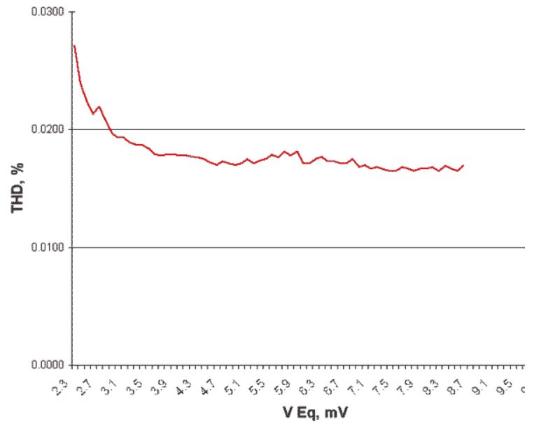
And indeed, as rightly pointed out by Ian Finch, one of the worst things that can be done to this excellent and beautifully sounding circuit design to ery low distortion, is just below the Bias Current/Voltage setting.
At 1 mV of adjustment, the Harmonic Distortion grows to unacceptable values and an odine larger than the ideal and better value which is equal to 0.0165%.
Below is the diagram relating to the THD distortion, in relation to the Bias regulation and not by chance the best values at which I impose it in my realizations is equal to 7.5/8.0 mV.
And just as important, with this control range, the power amplifiers, in addition to working in an ideal "linear zone", work in an absolutely perfect dissipation/SOA zone.
Last edited:
Yes, I have a NAP140 that has been on loan to an "old pal" for more than 20 years. He seems to think it's now his by right of possession but occasionally I drive the 500 km round-trip and use the opportunity to compare projects and clones built by local kids for fun. The debugged amplifier was one of a few items I took along recently for listening comparisons.
I have re-capped The NAP three times since I bought it, used. Since the "local" service agent may as well be located in Santa's workshop for what the service plus freight charges amount to here, this is the only sensible way, having done some routine service work on NAP models under guidance long ago. It's not rocket science, just systematic preventive maintenance that few manufacturers or consumers even consider.
I have re-capped The NAP three times since I bought it, used. Since the "local" service agent may as well be located in Santa's workshop for what the service plus freight charges amount to here, this is the only sensible way, having done some routine service work on NAP models under guidance long ago. It's not rocket science, just systematic preventive maintenance that few manufacturers or consumers even consider.
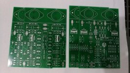
Thank you for the guidance, this is exactly what I have already built. I am using 30v dual secondary 500VA toroid with 6x10,000UF capacitors per channel. I have just used the PCB from zerozone , all the components are from digikey.Is this what you built (see photo)?
Rather than finding a NAP140 kit why not improve your Zerozone?
I guess the Zerozone NCC200 is a clone of the Avondale NCC200 which is a hacked version of the Naim NAP250.
You can give it a fighting chance by replacing the cheap capacitors and undoing the Avondale mods.
Build yourself a good power supply. This does not need to be complicated, just good. Copy Naim. Use proper quality psu smoothing caps like BHC or Mundorf, 10000uF per rail is plenty. Use separate supplies for each board (a dual secondary transformer is fine).
When you say "undo" the avondale bit, what do you exactly mean. Remove the coil from 13Ohm 3w resistor? I am using electrolytics instead of tants , but happy to change them if you suggest. Any other specific change in components that you would recommend. ?
Thanks
Would you post the Zerozone schematic?
A photo that shows the boards and the psu and the wiring would be good too.
A photo that shows the boards and the psu and the wiring would be good too.
Last edited:
That's a long journey.Yes, I have a NAP140 that has been on loan to an "old pal" for more than 20 years. He seems to think it's now his by right of possession but occasionally I drive the 500 km round-trip and use the opportunity to compare projects and clones built by local kids for fun. The debugged amplifier was one of a few items I took along recently for listening comparisons.
I have re-capped The NAP three times since I bought it, used. Since the "local" service agent may as well be located in Santa's workshop for what the service plus freight charges amount to here, this is the only sensible way, having done some routine service work on NAP models under guidance long ago. It's not rocket science, just systematic preventive maintenance that few manufacturers or consumers even consider.
May I ask what caps you recapped the psu with?
I enclose the relevant information you requested. Please note although the boards say "cerna Audio" and that is what I ordered , I have received Zerozone boards and schematics.Would you post the Zerozone schematic?
A photo that shows the boards and the psu and the wiring would be good too.
HTH
Attachments
Member
Joined 2009
Paid Member
oh my, a completely finished project for not very much wonga, makes DIY look like a labour of love doesn't it
Finished NAIM NAP 140 Amplifier Base on UK NAIM NAP140 Power amplifier 75W+75W | eBay
Finished NAIM NAP 140 Amplifier Base on UK NAIM NAP140 Power amplifier 75W+75W | eBay
Thats true, listening to ones own "labour of love" is a different experience, money can't buy. 🙂oh my, a completely finished project for not very much wonga, makes DIY look like a labour of love doesn't it
Finished NAIM NAP 140 Amplifier Base on UK NAIM NAP140 Power amplifier 75W+75W | eBay
Member
Joined 2009
Paid Member
Yup! - I'd drop 'x' grand on an amp tomorrow if I thought it would give me value for money - so far I never saw / heard one that would justify it. But my DIY amps are golden!
Sometimes you have to drop even more bullion on a decent DAC and speakers to get the full benefit.Yup! - I'd drop 'x' grand on an amp tomorrow if I thought it would give me value for money - so far I never saw / heard one that would justify it. But my DIY amps are golden!

Member
Joined 2009
Paid Member
I'm a bit, no, quite a lot, skeptical about high cost DACs. I think the industry jumped on that with great glee and affection for how much audiophool $ they can bathe themselves in. Speakers - they are the weakest link in my opinion, and a good speaker is very important.
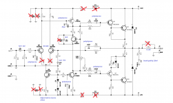
I've marked up the amplifier schematic with what I would do.I enclose the relevant information you requested. Please note although the boards say "cerna Audio" and that is what I ordered , I have received Zerozone boards and schematics.
HTH
--> No warranty implied <-- 🙂
You may get conflicting advice here (very rare in DiyAudio) and I am not always going to explain things because I am secretive. But you may want to assemble one board this way as a comparison.
Also, your transistors are not the Naim choices and not matched so this will cause an unpredictably worse result. Unless you use Naim's build process it will not sound as good as a Naim. It is up to you whether you decide to spend extra money on these parts.
Schematic changes
- Remove crossed out parts. Replace with wire as appropriate.
- Use 35V tantalums for C7 & C10. DOn't use lower voltage ones as they may not like being reverse biased during half the music signal. IF YOU ARE NOT EXPERIENCED building these then use electrolytics for power-on and once you are sure the dc offsets are ok then change to tantalums.
- the base networks on the darlingtons will not be correct for these transistors. I am not going to explain how to correct them but you stand a better chance if you use MJE243/253 drivers like Naim does.
- Inputs better with BC550C low noise.
- Adjust R26 (Q8 emitter resistor) to get the dc offset small. The BC546 is ok but it is different from the ZTX part Naim uses and the Vbe will be different.
- Remove output coil, replace 15ohm with 0.22.
Power Supply
The supply should be transformer with separate winding for each rail, two bridges & two smoothing caps per channel. Use good caps as I mentioned earlier. Don't wire lots of caps together. You need to be careful with your grounding paths. This is very important and there is lots of advice around here about that already.
I can't comment on the regulated supply yet. I need to find time to study it. But use the board unregulated to start with anyway. See how it sounds.
Attachments
Last edited:
Not everything that is expensive is bad. In audiophile culture, the source end is more important than the motor end. A mediocre DAC really costs you a lot of sound quality but I am rather out of touch about what are decent DACs these days. I bought a ML 39 many years back and it has been the best investment I have made for my music.I'm a bit, no, quite a lot, skeptical about high cost DACs. I think the industry jumped on that with great glee and affection for how much audiophool $ they can bathe themselves in. Speakers - they are the weakest link in my opinion, and a good speaker is very important.
Thank you so much for your kindness. Can I ask what ZTX part you are referring to ? This board is using ZTX 753 and 653 already?I've marked up the amplifier schematic with what I would do.
--> No warranty implied <-- 🙂
You may get conflicting advice here (very rare in DiyAudio) and I am not always going to explain things because I am secretive. But you may want to assemble one board this way as a comparison.
Also, your transistors are not the Naim choices and not matched so this will cause an unpredictably worse result. Unless you use Naim's build process it will not sound as good as a Naim. It is up to you whether you decide to spend extra money on these parts.
Schematic changes
- Remove crossed out parts. Replace with wire as appropriate.
- Use 35V tantalums for C7 & C10. DOn't use lower voltage ones as they may not like being reverse biased during half the music signal. IF YOU ARE NOT EXPERIENCED building these then use electrolytics for power-on and once you are sure the dc offsets are ok then change to tantalums.
- the base networks on the darlingtons will not be correct for these transistors. I am not going to explain how to correct them but you stand a better chance if you use MJE243/253 drivers like Naim does.
- Inputs better with BC550C low noise.
- Adjust R26 (Q8 emitter resistor) to get the dc offset small. The BC546 is ok but it is different from the ZTX part Naim uses and the Vbe will be different.
- Remove output coil, replace 15ohm with 0.22.
Power Supply
The supply should be transformer with separate winding for each rail, two bridges & two smoothing caps per channel. Use good caps as I mentioned earlier. Don't wire lots of caps together. You need to be careful with your grounding paths. This is very important and there is lots of advice around here about that already.
I can't comment on the regulated supply yet. I need to find time to study it. But use the board unregulated to start with anyway. See how it sounds.
I have ordered BUV20 NOS from USA, hopefully they would not be fake. I will order rest of the parts as per your advice and report back.
Regards
Last edited:
- Home
- Amplifiers
- Solid State
- NAP-140 Clone Amp Kit on eBay