I pulled few white resistors.the 3 i unsoldered all have 2.2-2 3 ohm resistance. Probably my meter. It's pretty accurate when measuring 180 ohm resistors. . Reads 178.8ohm.
Where are driver transistors? Will check output transistors. . Don't those always blow or short.. and cause dc relay to turn on.
I've read somewhere diode or resistance test of output transistors is not the best way to test them.
But if measuring voltage when amp is hot and running should I attach meter terminals to base and emitter? I assume those transistors by heat sink are all BCE labeled from right to left
Last edited:
Do you have the Service manual?
It can be downloaded at "https://www.hifiengine.com".
The transistors attached to the heat sink are the drivers, outputs and the bias transistors.
Easily seen at page 26 in the service manual, if you compare withe schematics on page 36.
It can be downloaded at "https://www.hifiengine.com".
The transistors attached to the heat sink are the drivers, outputs and the bias transistors.
Easily seen at page 26 in the service manual, if you compare withe schematics on page 36.
This 'floating woofer' fault wouldn't immediately make me suspect a semiconductor. Its an odd fault with a large time constant thatis causing the DC conditions to slowly change.
Its scope and signal generator territory I'm afraid as far as proper fault-finding goes but you never know, you might get lucky.
Its scope and signal generator territory I'm afraid as far as proper fault-finding goes but you never know, you might get lucky.
I am just thinking of replacing stupidly everything in power amp section.. not to expensive. Diodes, resistors.. capacitors. Will make list and would no doubt need advices to get the proper equivalents
That's a sure-fire way to disaster imo, and its certainly no way to fault find.
Replacing all the semiconductors with equivalents will almost certainly lead to other problems appearing... things such as being unable to set the bias correctly (or worse it having a high initial bias that could be destructive). Stability issues could arise that would need an experienced tech with the correct equipment to diagnose and redesign for.
Its great that you want to have go, but swapping everything in sight isn't the way forward.
I see. What about those variable resistors to adjust bias? Ice heard some people complain that they often don't hold resistance. I might swap those left to right. Then maybe driver transistors. I understand issues when. Using transistor equivalents. But resistors, diodes.. capacitors should be easy to find with exact specs
Doing what you propose will end in tears because (and with the very greatest respect) you haven't got the theoretical knowledge of how it all works and what the problems would be.
Varying bias in itself would not alter the DC voltage conditions at the output. You have no need to swap bias presets to prove them (that could be disastrous anyway), all you need do is force a zero bias condition by linking the vbe multiplier transistor out.
In the first instance you should be doing diagnostic tests and gathering as much evidence of the fault as possible.
I completely understand the importance of knowing or having a slight idea of how amplifier works before doing anything. Problem is .. I don't know of any good tech who actually knows what he is doing.. 75$ to pUT it on the bench and stare at amp.
I not too worried if something blows. I'll be using speakers I don't care about with this amp.
Ill try swapping output transistors in pairs from side to side.. I just don't see how this can possible create a disaster of global proportion. Maybe buying paired 1492 3856 transistors from digikey will be a good option if output transistors prove to be bad. Have thermal paste.
As you are determined to have a go without proper test equipment then the first thing I would do is see if the bias actually adjusts correctly i.e. you can turn it up and down and see the corresponding rise and fall in the current.
I would then swap the power amp inputs over (left to right) and see if the problem stays on the same channel or not.
I would then swap the power amp inputs over (left to right) and see if the problem stays on the same channel or not.
Well it wasn't
Driver or small transistors on heat shields.
Not variable resistors to adjust bias
Not output transistors.
I swapped everything in 3 steps. Swap and test.
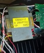
What looks like a problem is transformer.
I unplugged cn12 and cn11.
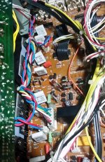
A pair of blue and red wires on left and right channel.
There is also a pack of 6 wires that go from main board to speaker terminals.
I plugged cn12 into cn11(left).. and got really high bias viltage.. 40 or 45mv
Then it started to come down to around 30mv.
Exact same behavior when cn12 was plugged into right channel.
Originally left channel had bias at 27mV.
And of course another tragedy happened.. I shorted bias terminals on left channel. Heard something blow.. but can't see what cracked or broke.
Attached is the pic of those pairs of blue and white that I spoke about. And a pic of transformer..maybe it's not original
Driver or small transistors on heat shields.
Not variable resistors to adjust bias
Not output transistors.
I swapped everything in 3 steps. Swap and test.
What looks like a problem is transformer.
I unplugged cn12 and cn11.
A pair of blue and red wires on left and right channel.
There is also a pack of 6 wires that go from main board to speaker terminals.
I plugged cn12 into cn11(left).. and got really high bias viltage.. 40 or 45mv
Then it started to come down to around 30mv.
Exact same behavior when cn12 was plugged into right channel.
Originally left channel had bias at 27mV.
And of course another tragedy happened.. I shorted bias terminals on left channel. Heard something blow.. but can't see what cracked or broke.
Attached is the pic of those pairs of blue and white that I spoke about. And a pic of transformer..maybe it's not original
Attachments
Last edited:
So after that left channel bias short.. left channel bias voltage is .33V..
As apposed to mV.
Right channel is fine. 10mv .
Amp stays in protection if both cn11 and cn12 rails are plugged in.
If the left channel (cn11) is unplugged amp powers up and speaker relay clicks.
As apposed to mV.
Right channel is fine. 10mv .
Amp stays in protection if both cn11 and cn12 rails are plugged in.
If the left channel (cn11) is unplugged amp powers up and speaker relay clicks.
Doing what you propose will end in tears because (and with the very greatest respect) you haven't got the theoretical knowledge of how it all works and what the problems would be.
I thought something like this would happen.
The power amp is a fairly simple design and as long as it has got its correct supplies present then it should all work correctly.
Swapping wires around from the transformer doesn't sound a good idea. You are introducing far to many variables to make sense of it all.
If you have the plus and minus rails present on the amp board then that is self contained as far as fault-finding goes. All the evidence as to what is wrong will be in the voltage measurements.
I think you have to accept that this is perhaps going to be above your capabilities to resolve. It needs proper methodical fault-finding, not random swaps of parts.
Hm. Yes) u definitely sound like u saw a lot of such "ends in tears")
I'll put this amp on the shelf .. maybe by the end of my life I'll figure out what the problem is.
But as far as shorting bias terminals.. I am sure this was done many times. Is there any particular spot or component That normally fails? Like resistor/fuse .
I hope bias can only damage power amp section.
Or its a complex issue
Shorting the bias transistor (the vbe multiplier) from C to E forces a zero bias condition. That is safe to do.
Output transistors, drivers and any low value resistors in the vicinity are the only real casualties of high bias that becomes destructive.
Output transistors, drivers and any low value resistors in the vicinity are the only real casualties of high bias that becomes destructive.
Hello again!
So you shorted at the bias testing pins on the left channel, that would probably kill Q262L and hopefully nothing else.
The initial high bias voltage you saw when swapping CN11 and CN12 was probably just heat related, what I've seen is that bias normally is higher when the unit is cold and will gradually go down and stabilize as temperature goes up.
Is it 33V or 0,33V on left channel bias check point?
You could probably safely remove Q262L and Q264L to see if left channel comes back to life. But just for a short while as bias could be twice as high on the remaining outputs and you wouldn't be able to get any readings on the bias test pins on left channel with Q262L gone.
The CN11 and CN12 cables has the same power source, so I wouldn't suspect them unless there is some damage on them.
As for the floating bass issue, I guess you eliminated Output/Driver/Bias transistor problems by swapping those.
- Status
- Not open for further replies.
- Home
- Amplifiers
- Pass Labs
- Nakamichi stuck in speakers A all the time.