I see. Yes I think I'll need to investigate myself.. there is only That much that can be done over online communication.. but still it's extremely helpful.Those could be test points for setting bias current... highly likely given their location.
With Q272/274 removed then the relay that they control should not operate. You need to confirm that by observation and making sure that the relay does not now have any voltage across the coil.
You still have the other pair of transistors and the relay that they control.
If you are not sure what goes where then you need to trace the speaker feed that isn't behaving correctly back to the relay. That is the only sure way you will identify it. You can then see if that relay is behaving or not. When a relay opens the circuit is broken and the speaker should go silent.
Would u tell me what other pair of transistors turn the relay on? Basically I'll await for new transistors. . And in the mean time will trace speaker wires back to relay. Well compare speakers b and speaker a pathways.
Can a relay be mulfunctioning? It does not appear to be sricky.. clicks, disconnects
Very unlikely to be a faulty relay. They either open and close or they don't.
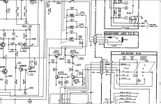
Here is a more complete diagram. Look at the two points marked A and B on the selector PCB connector CN7.
When A has 5 volts present Q272 and 274 turn ON and relay RY250 operates connecting the speakers.
When B has 5 volts present then Q271 and 273 turn ON and relay RY251 operates.
When A and/or B are at zero volts then the appropriate relay is OFF.
The switching allows either A or B or both A and B as valid on states.
Relay RY252 is controlled from elsewhere on board.
Attachments
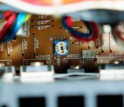
WTF, look at the first picture you posted in post 38, relay RY250 is replaced with two resistors it seems.
(RY250 = Relay for Speaker A )
The dude who did that was eh, hum, "creative" ;-p
(RY250 = Relay for Speaker A )
The dude who did that was eh, hum, "creative" ;-p
Last edited:
Holy F.. yes you are 100% right..WTF, look at the first picture you posted in post 38, relay RY250 is replaced with two resistors it seems.
(RY250 = Relay for Speaker A )
The dude who did that was eh, hum, "creative" ;-p
Classic ebay merchandise.
I've heard stories about people buying high end stuff on ebay swapping hard to find parts and then arguing item was defective. Seemed too shady for me. Real life experience) first hand.
Attachments
Last edited:
Would this affect sound quality? Need to try uploading a video.. but during bass heavy tunes woofers kind of float too much. Hard to explain. But basically can stay in or out for longer time. Not fast bass. Other amps don't do it on same tracks. This behavior is noticeable a little bit on other amps but not to the degree of ta-4a.
Thank you very much everyone..
But if I just use speakers B.. will this trick by previous owner have any affect on the sound? Can I unsolder those resistors? Without problems. Well till I get new relay
Thank you very much everyone..
But if I just use speakers B.. will this trick by previous owner have any affect on the sound? Can I unsolder those resistors? Without problems. Well till I get new relay
Last edited:
Yeah, you can remove them and just use B Speaker.
They shouldn't affect sound on B if left in place tho.
They shouldn't affect sound on B if left in place tho.
And are there any new relays that I can buy anywhere besides ebay? An improved super low resistance. .things like that. Basically it's really on and off switch.
Is there a trusted brand of aftermarket relays. That can be same as oem or better. I've seen a few of these relays on ebay
Is there a trusted brand of aftermarket relays. That can be same as oem or better. I've seen a few of these relays on ebay
And just one quick question. Those q274 and q272 won't be active or affect sonics if i leave them off for now right?
Basically I wanted to put the amp together more or less and investigate bass performance till relays and new transistors arrive. I'll only use speakers B for now
Basically I wanted to put the amp together more or less and investigate bass performance till relays and new transistors arrive. I'll only use speakers B for now
And are there any new relays that I can buy anywhere besides ebay? An improved super low resistance. .things like that. Basically it's really on and off switch.
Is there a trusted brand of aftermarket relays. That can be same as oem or better. I've seen a few of these relays on ebay
These will fit:
G2RG-2A4 DC24 Omron Electronics Inc-EMC Div | Relays | DigiKey
And just one quick question. Those q274 and q272 won't be active or affect sonics if i leave them off for now right?
Basically I wanted to put the amp together more or less and investigate bass performance till relays and new transistors arrive. I'll only use speakers B for now
Those transistors purpose is only to operate relay RY250 and has nothing to do with the signal path.
So here is the issue with "floating " woofers. Only right channel does this.
Ta3a normal movement
https://vid.me/dKjY
Ta4a floating woofers
https://vid.me/Mlyv
Its not speakers.. I swapped wires.
Balance is dead on center.. maybe check bias? I have not clue how to do it.. maybe one channel Is getting a lot more current than the other
Ta3a normal movement
https://vid.me/dKjY
Ta4a floating woofers
https://vid.me/Mlyv
Its not speakers.. I swapped wires.
Balance is dead on center.. maybe check bias? I have not clue how to do it.. maybe one channel Is getting a lot more current than the other
Last edited:
Also right channel( with floating woofers) has pronounced highs. Left channel sounds like it has tremble all the way down. I did clean all pots. Variable loudness too.
Seems like I need to confirm this amp has all components in there. This ebayer sounds like scam.
Seems like I need to confirm this amp has all components in there. This ebayer sounds like scam.
Could not find instructions on how to adjust bias on solid state. Nakamchi in particular. Internet is trashed with guitar amp bias adjustment.
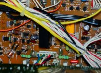
I think those 2 blue white variable resistors is what needs to be adjusted. They seem way too off of each other.. usually these pots are in more or less similar position.
I think those 2 blue white variable resistors is what needs to be adjusted. They seem way too off of each other.. usually these pots are in more or less similar position.
Attachments

Small BUT pertinent point: WHY ? is
Some dopey/broken Nak issue continuing.. in the Pass forum?
Mods having a Nap?
Some dopey/broken Nak issue continuing.. in the Pass forum?
Mods having a Nap?
Small BUT pertinent point: WHY ? is
Some dopey/broken Nak issue continuing.. in the Pass forum?
Mods having a Nap?
Would you be so kind as to please contribute to other threads. I Am Having the Time of my life working On this unit. . And actually learning a lot. I know its weekend.. drinks.. unsuccessful hook up attempt. Rage frustration..
Can u actually look into those variable resistors.. and help me understand how to adjust.. and measure bias.
I believe you cAn be A Very helpful poster. Good amps. Worth time money and everything. Life would not be the same for me without Stasis..
Measured voltage at those 2 terminals it was 12 and 30mv.
After cleaning variable resistors with deoxit f5 adjusted idle bias to 22.5mv each channel
After cleaning variable resistors with deoxit f5 adjusted idle bias to 22.5mv each channel
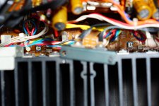
One thing I noticed.. right channel runs much hotter than left.
I followed bias adjustment procedure. Left amp at min volume, speakers off position for 10 min.
Adjusted bias to 27.5mV. Botherwise channels
After playing music for 15min I noticed right channel is much hotter. Heat sinks are very hot.
Set speakers to off. Disconnected everything, volume at minimum
Now right channel bias is 50-55mV
Left channel 22mV.
After 3-4 min of idle biases come back to 27.5mv.
I am thinking those variable resistors don't hold resistance well. I have read some people use regularge resistors of set value.
Also dc offset is 43mv on right channel
10mv on left channel.
Last edited:
WTF, look at the first picture you posted in post 38, relay RY250 is replaced with two resistors it seems.
(RY250 = Relay for Speaker A )
The dude who did that was eh, hum, "creative" ;-p
Well spotted 🙂
I wonder if they are for some weird headphones or something.
----------------------------------------------------------------------
This 'floating woofer' issue looks odd. For the woofer to move like that suggests that there is a shift in the DC conditions as the amp pumps current into the speakers.
I would attack that issue with a scope and look at the input signal to the power amp (to see if the shift is appearing there) and also to look at all the rails under load. There are no servos, no auxiliary rails to the power amp... so that is an add issue for sure.
Also, based on what has come to light in the last few hours it could well be another manmade fault.
So I think I'll deal with floating woofers later. It's most likely a power amp issue. Just checked. When used as pre amp ta-4a sounds good. No floating woofers
But as far as those relays.. u think 8A max current is enough? Doesn't this amp put out close to 16-20 amp per channel? Is this relay high current relay or blocks dc current at low voltage /preamp stage
Last edited:
- Status
- Not open for further replies.
- Home
- Amplifiers
- Pass Labs
- Nakamichi stuck in speakers A all the time.