An easy way to determine if the problem with the floating woofer is in the power amp section or in the pre amp section is to replace the pre out/in jumpers on the back at the unit with rca cables.
(Just saw that you already checked this.)
Then you can attach them "left out -> right in" and "right out -> left in", to see if the problem changes side.
But the combined issues on right side with heat, fluctuating bias, high dc-offset (not alarming high tho) and floating woofers, makes me think there is a problem with driver/output transistors.
On SR-2,3 and TA-2 I've gained lower DC-offset (roughly 15-25mV) and tighter and more detailed bass reproduction after changing the drivers.
(new matched differential pair lowers DC-offset about as much as new drivers on those units, usually ends up with a DC-offset between 0 too 10mV.)
If it was a power supply issue it would affect both channels (unless there is a problem with the cable that is feeding the right side.).
All I could think about at the moment.
Last edited:
So I think I'll deal with floating woofers later. It's most likely a power amp issue. Just checked. When used as pre amp ta-4a sounds good. No floating woofers
But as far as those relays.. u think 8A max current is enough? Doesn't this amp put out close to 16-20 amp per channel? Is this relay high current relay or blocks dc current at low voltage /preamp stage
It was the highest current relay, with the right dimensions that I could find last time I checked. And the TA-4 can momentary push 28A per channel according to specs.
(but that would be into an extremely low impedance load for that to happend.)
Bare, it is a Nelson Pass designed STASIS amp, licensed to Nak so we saw no harm in leaving it here. The OP must have known that too.Mods having a Nap?
Few other options for relays. To compare.
G4W-2212P-US-TV5-HP-DC24 Omron Electronics Inc-EMC Div | Relays | DigiKey
G4W-2214P-US-HP-DC24 Omron Electronics Inc-EMC Div | Relays | DigiKey
RP440024 TE Connectivity Potter & Brumfield Relays | Relays | DigiKey
I am just thinking that 20-25 amp relays is an overkill.. those wiring on the board I doubt can handle 16 amp or higher current
Board will fry.
And 20a + relays look like need thick wires. Not tenth of a millimeter connection
There is no info in manual on the specifics of this relay.
Basically turn off dc voltage of nonmore than 2v dc?
Relatively quickly. 5ms?
Would be good to know general guidelines. Hopefully new relay will be an upgrade. Faster turn off time at dangerous dc voltage.
What other parameter are crucial?
U mentioned current in q272 or q274 is 30ma? Basically it's the operating current I need to look for I guess
Last edited:
Few other options for relays. To compare.
G4W-2212P-US-TV5-HP-DC24 Omron Electronics Inc-EMC Div | Relays | DigiKey
G4W-2214P-US-HP-DC24 Omron Electronics Inc-EMC Div | Relays | DigiKey
Tho the electrical specs on these two are fine, their physical size will make them tricky to fit.
The transistors I suggested earlier might be too weak, they have a Ic max of 50mA and as the relay will draw 30-33mA it might lower the life span on them.
On the other hand they have a higher wattage, 0,5W, compared to the old ones 0,3W.
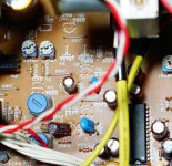
What about these white resistors.. they all measure 2.5ohm in circuit. But labeled different. On the left channel 2 were unsoldered it looks like. Replaced. Mpc71 instead of mpc74
Right channel 2 are mpc74. 1kohm. Fu589H
And 2 are mpc74 1kohm fu589K
Left channel 3 are mpc74 1kohm fu589k
And one is totally different mpc71 1kohm. Fu0
Right channel 2 are mpc74. 1kohm. Fu589H
And 2 are mpc74 1kohm fu589K
Left channel 3 are mpc74 1kohm fu589k
And one is totally different mpc71 1kohm. Fu0
Attachments

Last edited:
Could not find anything obviously blown..
Might swap output transistors from channel to channel to see if they are the issue..
Could fluctuating dc voltage be rectifier diode failure symptom? Bridged in power supply. I found where power amp section starts. . Just doubt it's one of the semiconductor components. . Don't they blow and fail 99.999% of the time? With Cracks or burns.
If a diode in the bridge went short then it would blow a fuse. If one went open then the regulation of the supply (and the ripple) would suffer but I doubt it would be enough to cause this problem.
You really need proper test equipment such as a scope for working on these faults 🙂
You really need proper test equipment such as a scope for working on these faults 🙂
If a diode in the bridge went short then it would blow a fuse. If one went open then the regulation of the supply (and the ripple) would suffer but I doubt it would be enough to cause this problem.
You really need proper test equipment such as a scope for working on these faults 🙂
I agree.. in the past I had visible clear problems. Something blew.. leaked capacitor. Ill keep swaping left and right channel components to see which one is at fault. Its like yoga for me )) good thing problem zoomed in on power amp section.
Just one question. This amp has one transformer. Does it feed both channels? Where do 2 channels separate. Become different paths
Need to read up on transformers role.
.I've heard it's transforming high voltage low amps into low voltage high amps.
Finding a competent tech I think is even more of a challenge than fix this amp yourself.
Most people are good at posing like they know whats up with a charming smile.
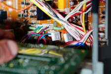
I kind of see power amp section of this amps is by heat sinKS
.there are 2 3 pin cables coming from input RCAs intone board
Last edited:
I've blown a couple of outputs and drivers and none of them shoved any visible damage.
Those resistors you asked about are the emitter followers.
On my unit they all measures to 1.2 -1.3 Ohm.
If all yours measures to 2.5 Ohm, I'd guess that it's your multimeter that doesn't show accurate readings on low resistance.
So they seem to be fine.
(Below here I might be totally wrong in my assumptions)
It's over one of those on each channel the bias is measured.
It might reveal something if you measure the bias for each transistor over their corresponding emitter follower.
BUT BE CAREFUL IF YOU DO, dead transistors will be the result if you slip with the probes.
Out of curiosity I did it on my unit.
Left channel they all had 15-16mV
Right channel they all had 26-28mV
(Yeah, I should adjust bias ;-p )
(When I think about it, one bad driver would affect bias on all outputs)
If one differs a lot from the others that transistor might be faulty.
But if they differs in pairs, for example Q261R and Q262R resistors shows around 28mV
And Q263R and Q264R shows 14mV.
Then I would suspect one of the drivers, Q259R or Q260R.
Which one would be hard to tell, I'd change both.
Last edited:
Just one question. This amp has one transformer. Does it feed both channels? Where do 2 channels separate. Become different paths
Need to read up on transformers role.
.I've heard it's transforming high voltage low amps into low voltage high amps.
Yes, the power supply is common to both channels and so that pretty much rules out anything bridge or reservoir cap related.
The transformer delivers low voltage AC from the much higher mains voltage and also provides the vital role of ISOLATION from the mains 🙂
Or if some one knows of a competent tech who can dearly show me the problem on east coast of usa(ny. Nj, mass, connecticut, Rhode island).. That would be good. I am off to another business trip. For few days. I think I'll be measuring voltages by output transistors to see which one over or under performs when I am back. Checking resistance when amp is cold does not tell much does it?
You can't check resistors in circuit as a general rule although for values under say 100 ohm then often you can get a meaningful reading that they are OK.
If you short your meter leads together then the reading should be 0.00 ohms. Anything over that is going to be primarily the meter lead resistance adding to the result. The meter should always read 0.00 give or take a single digit when you firmly short the terminals.
If you short your meter leads together then the reading should be 0.00 ohms. Anything over that is going to be primarily the meter lead resistance adding to the result. The meter should always read 0.00 give or take a single digit when you firmly short the terminals.
I see.. I'll unsolder those white resistors. .measure them. Then get to output transistor swaps. Good to know about resistance in circuitYou can't check resistors in circuit as a general rule although for values under say 100 ohm then often you can get a meaningful reading that they are OK.
If you short your meter leads together then the reading should be 0.00 ohms. Anything over that is going to be primarily the meter lead resistance adding to the result. The meter should always read 0.00 give or take a single digit when you firmly short the terminals.
You do know you measure resistance with the amplifier OFF.
Had to ask 🙂
Yes those 2.5 ohm measurements were made with amplifier off. But video board was unplugged during measures. I'll plug it back in and see if I get 1.3-1.5 ohm readings. Multimeter.. Hm does read 0 when both terminals are shorted.
Edit
Really sorry about these typos which made this post the opposite of what I tried to convey in english.
Last edited:
- Status
- Not open for further replies.
- Home
- Amplifiers
- Pass Labs
- Nakamichi stuck in speakers A all the time.