Yes meant Thermistor. I pulled 1 leg of thermister from the board and just heat from soldering iron made it drop resistance fast. It. went down to about 600 ohms. When it fully cooled it was about 1200 ohms.You mean thermistor , NTC ? Personally I have never encountered a failed thermistor in such applications. Well, mechanically damaged yes. Check the resistance of that NTC when cold and report here. Btw, you could place a fixed resistor for the sake of quick testing but beware, without thermal tracking, the output transistors might go bang due to the thermal runaway. Q139 is there for the same purpose. Keep it mounted on the heat sink all the time while testing.
Q114 and 115 are the hot ones in a very short period. The others do heat up over time. I felt of every big transistor and only Q125 seems hotter than the others. The only resistor that seems to be different than others is R141. It seems to be about .002 to 004 volts higher than the rest depending on how long its been on. The transistor associated with it does not seem warmer than the others though.Above post remains my favorite conjecture about possible defect. But I would add Q120 through Q133 as additional suspects; I believe open collector junctions could cause similar symptoms. And please reconfirm Q116-119 are the devices that are inordinately hot.
Re the emphasized print above, are any of the 14 resistor voltages dramatically different than 0.036V? (i.e. R130 though R143). Any such associated transistors may be suspect re wg_ski quote above. What are voltages across R126 through R129?
Thanks!
Yes Q114 and 115 are hot ones. Q116 to 119 seem same temps as rest. Q 125 does seem hotter than the other big ones but no where near 114 and 115. No not trolling.+1
That could definitely clear up a lot of things. Now I'm not sure anymore which ones are getting too hot, Q114/Q115 or Q116-Q119 !?
@gto127, are you trolling us ? 😆
😉

No not trolling.
I was joking. 😉
Ok, as BSST suggested, measure the voltages across resistors, R126 to R129. Set (somehow) the bias 40mV (TP11) do the measuring and switch it off. Leave the bias trimpot in that position. When the whole thing cools down, power it up and check the voltages across all emitter resistors from R124 to R143. Write all readings down on a paper so that we can have a better picture of what's going on. Without checking voltages across all emitter resistors we will still sit in the dark. Well, DMM attached to TP11 points is actually measuring voltage across R136 already. 😉
Last edited:
Thats basically what I did was set it to 40mv letting it cool cutting on but when cool the bias starts out higher and goes down to 40 over mabye 10-15 minutes. Thats why i said they are the same with exception of R141. They are constantly changing on the way down but are the same when you measure adjacent resistors with exception of R141 and of course R124 &125 which are quite a bit different @ .6volts eachI was joking. 😉
Ok, as BSST suggested, measure the voltages across resistors, R126 to R129. Set (somehow) the bias 40mV (TP11) do the measuring and switch it off. Leave the bias trimpot in that position. When the whole thing cools down, power it up and check the voltages across all emitter resistors from R124 to R143. Write all readings down on a paper so that we can have a better picture of what's going on. Without checking voltages across all emitters we will still sit in the dark.
Tell me about R141 voltage. This may be key!Thats basically what I did was set it to 40mv letting it cool cutting on but when cool the bias starts out higher and goes down to 40 over mabye 10-15 minutes. Thats why i said they are the same with exception of R141. They are constantly changing on the way down but are the same when you measure adjacent resistors with exception of R141 and of course R124 &125 which are quite a bit different @ .6volts each
Thats basically what I did was set it to 40mv letting it cool cutting on but when cool the bias starts out higher and goes down to 40 over mabye 10-15 minutes.
That's OK and that means the thermistor (TH11) and Q139 are doing their job right. So no problem with the Vbe multiplier.
and of course R124 &125 which are quite a bit different @ .6volts each
Good. That's OK as well.
Edit: BSST already posted. Good. 🙂
Last edited:
R126 through 129 are same depending on how long its been on. 40mv after warm up. I just reconfirmed Q125 does get hotter than the rest especially after a few minutes. The rest are still relatively cool when it starts getting hot. I know you normally have to replace complimentary pairs when replacing transistors but this has alot. Could I just replace a couple to see if this is the culprit or would I have to replace whole bank?That's OK and that means the NTC (TH11) and Q139 are doing their job right. So no problem with the Vbe multiplier.
Good. That's OK as well. What are the voltages acros R126 - R129 ?
Edit: BSST already posted. Good. 🙂
You still haven't told me about R141. But also tell me about Q125 and its emitter resistor R135.
You still haven't told me about R141. But also tell me about Q125 and its emitter resistor R135.
+1
R141 .045v and R135 .039vYou still haven't told me about R141. But also tell me about Q125 and its emitter resistor R135.
R141 .045v and R135 .039v
That's not a huge difference. Probably output transistors are not perfectly matched + resistor tolerances. Not a big deal. To me the output is working OK.
The problem is that I can't see it ! Guys, maybe I'm too old ! 😢
Q125 seems suspicious, since you report that it's hotter than its companions, yet its R135 bias voltage is a bit smaller. R141 is similar to other neighbors and its Q131 transistor seems typical re temperature?
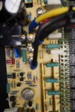
It's very difficult for me to interpret, but it appears that the board seems to feature some jumper wires that would allow Q125 emitter and perhaps base to be removed from circuit. Would you explore if that's an easy experiment? The idea would remove temporarily Q125; then you would readjust bias and check if operating temps seem more reasonable. (Don't connect any load; number of transistor its unbalanced but this shouldn't matter for debug test.)
I have to run errands for a couple hours but will return.
BTW, I don't think you will have to match transistors.
I measure rest of transistors on that side(according to schematic) Only Q127 has simuliar measurements but instean of .17 its .04 at same point. The other transistors in this bank are 78, 77.3 and ..04Voltages on Q125 are .17 77.9 and .7
I will sit in the corner and watch. Btw my last two cents, what about the offset voltage now after finding some dodgy resistors ?
I measure rest of transistors on that side(according to schematic) Only Q127 has simuliar measurements but instean of .17 its .04 at same point. The other transistors in this bank are 78, 77.3 and ..04
Attachments
- Home
- Amplifiers
- Solid State
- Nakamichi PA7II- are 2SA1837 and 2SC4793 suitable replacements for 2sc3298 and 2sa1306 in this amp?