All my parts are from mouser to avoid fakes.
for your simulations on Ltspice i can't answer you i don't use Ltspice.
i just visualise music signal on my oscilloscope playing on a speaker but it's with normal volume can't do at hight power for my ears ^^
for your simulations on Ltspice i can't answer you i don't use Ltspice.
i just visualise music signal on my oscilloscope playing on a speaker but it's with normal volume can't do at hight power for my ears ^^
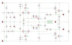
I would remove, at least - for sound reasons:With 100ohms works well. That schematic physically tested. Don't care R10,R3 values.
View attachment 1151502
R4, R19, R23, D2, D5, D6, D7, C3, C7, C9, C10

I would remove, at least - for sound reasons:Sin wave looks good, so 🙂
Add some 1uf capacitor, 100nf also. This is texas inst. power supply design. (test it if you want)View attachment 1149741
Cs1, Cs2, Cs6A,B, Cs5A,B, Cs8, Cs7, Rs2, Rs1,
Cs11, Cs12, Cs13, Cs14
reg = transistor and more.Testing regulated vs. raw at the power stage it seems to me that the raw supply sounds more voicy, cleaner, and bouncier than regulated, but regulated sounds more tidy and also tighter.
The most transistors are unsuitable for audio. And every bipolar transistor draws a small fine veil into the sound image. The advantage "tidy and also tighter" is bought with the disadvantage more incoherent, more unmusical, more disembodied; more technical, artificial.
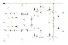
I started to take a closer look at the regulation map.
I noticed that in the RC circuit the value of R111 is different on your jpk43 version with the BDY58 output compared to the other versions on the 001. It is 680 ohms with the 001 against 1000 ohms on your jpk73 version. can you confirm this for me?
I didn't see any other difference.

I noticed that in the RC circuit the value of R111 is different on your jpk43 version with the BDY58 output compared to the other versions on the 001. It is 680 ohms with the 001 against 1000 ohms on your jpk73 version. can you confirm this for me?
I didn't see any other difference.
![DSCN0264[1].JPG](/community/data/attachments/1061/1061568-e23ac9a506be48cfc9439970dcacb8bc.jpg?hash=4jrJpQa-SM)
I started to take a closer look at the regulation map.
I noticed that in the RC circuit the value of R111 is different on your jpk43 version with the BDY58 output compared to the other versions on the 001. It is 680 ohms with the 001 against 1000 ohms on your jpk73 version. can you confirm this for me?
I didn't see any other difference.View attachment 1153541View attachment 1153542
I checked: 1K is correct!
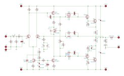
I have a question about those resistor values in the compensation networks. Looking at the schematics it seems to me that if we take the values Naim used for the 001 transistors we always end up with +20% in the positive circuit. In attached schematics I marked the positive resistor in red and the negative in blue. So: the NAP has 470 and 390 (390 + 20% = 470), the Naim regulator has 680 and 560 (560 + 20% = 680), and Jeff' inverted regulator has 120 and 100 (again +20%). Now if I take the values for the BDY58: the regulator has 1K and 560 which is +180% - would it be correct to assume that in Jeff's regulator we would need 180 and 100 for BDY58s...?
Attachments
Ty for your answer. It s a good question. I do tests on regulatory board i will post pics tomorrow. I replace the r111 by a variable resistor for testing and i dont see Any difference on my oscilloscope with my laboratory supply. But it s at 30volts while it s 60volts on the Real amp. I will do some tests on my old amp.
Now if I take the values for the BDY58: the regulator has 1K and 560 which is +180% - would it be correct to assume that in Jeff's regulator we would need 180 and 100 for BDY58s...?
Sorry a typing mistake: of course I meant +80% (=180%), not +180%...
First of all I did tests on my laboratory power supply with my test PCBs by replacing the output capacitors of the regulation board (esr about 200 mOhms) with standard ones (ESR 2.6 ohms) I didn't I haven't noticed any improvement in terms of stability, on my old amp the drivers for the regulation card are 2n5192/95.

here 20Khz up trace is amp, low trace is a supply rail you see about 400mv of travelling (my scope probes are X10)

And with 10Khz/100mv with 1 UF capacitor about 800mv of travelling the ragulator board is not very stable

I then replaced it with the original ones (Mj243/253) and capacitors
the improvement is clear with the original drivers the card is more stable it is also better with the low esr capacitors. About 400 mv of travelling on 10Khz 1uF capacitor:

on 20Khz 100mv i have a better trace

I then made measurements on my old amp and it was not brilliant I had a travel of more than 3 volts on the regulation card when I entered a signal of 1 volt on a load of 6.8 Ohms.
With a capacitor of 1 Uf in parallel the deflection increased significantly.
here a trace at 10 Khz you see phase problem and bad trace on a supply rail

Once the regulation and amplification card has been replaced in my old amp, the results are much better concerning the regulation card, I only have 500 mv of travel instead of the more than 3 volts before. it's even better than on the laboratory supply
The trace is much finer much less noisy I initially had around 20-30 mv of noise against 6-7 mv now on the positive rail and even less on the negative rail around barely 1 mv (which is starting to be difficult to visualize on the oscilloscope)
The amp is stable although not wonderful on a 1uF load either, but with the transistors wired up it certainly doesn't help.
Listening to the changes bring a little more in terms of scale even if it is not day and night!
I will then go to my new amp to modify it and test what it gives. If everything works well then I would modify the other channel of the old one.
here 20Khz up trace is amp, low trace is a supply rail you see about 400mv of travelling (my scope probes are X10)
And with 10Khz/100mv with 1 UF capacitor about 800mv of travelling the ragulator board is not very stable
I then replaced it with the original ones (Mj243/253) and capacitors
the improvement is clear with the original drivers the card is more stable it is also better with the low esr capacitors. About 400 mv of travelling on 10Khz 1uF capacitor:
on 20Khz 100mv i have a better trace
I then made measurements on my old amp and it was not brilliant I had a travel of more than 3 volts on the regulation card when I entered a signal of 1 volt on a load of 6.8 Ohms.
With a capacitor of 1 Uf in parallel the deflection increased significantly.
here a trace at 10 Khz you see phase problem and bad trace on a supply rail
Once the regulation and amplification card has been replaced in my old amp, the results are much better concerning the regulation card, I only have 500 mv of travel instead of the more than 3 volts before. it's even better than on the laboratory supply
The trace is much finer much less noisy I initially had around 20-30 mv of noise against 6-7 mv now on the positive rail and even less on the negative rail around barely 1 mv (which is starting to be difficult to visualize on the oscilloscope)
The amp is stable although not wonderful on a 1uF load either, but with the transistors wired up it certainly doesn't help.
Listening to the changes bring a little more in terms of scale even if it is not day and night!
I will then go to my new amp to modify it and test what it gives. If everything works well then I would modify the other channel of the old one.
For a speaker HF capacitance may be 5, 6uf. But, for LF it must be less than 1uf. -> for the testing 1uf may be too big for a speaker. What do you think about that?
1uf it is for testing the stability of the amp. Testing on a Real speaker world be the best sting but not for ears unfortunatly
Looks quite similar to my scope shots I posted, no? I guess the voltage is supposed to sag a little bit under such extreme stress (droop), but current is delivered, hence the amp trace looks fine.I had a travel of more than 3 volts on the regulation card when I entered a signal of 1 volt on a load of 6.8 Ohms.
Last edited:
Ok on my laboratory supply i don't see any oscillations with low esr capacitors.
in the real amp it's more delicate maybe i will test a second time with normal esr capcitors if i see problems
in the real amp it's more delicate maybe i will test a second time with normal esr capcitors if i see problems
This seems to be the case in the amplifier with my frequency generator I can see a small oscillation that you didn't see when the boards are powered with the lab power supply and besides I don't understand why.
Before I used a laptop PC to generate the signals and it was not visible besides we could not really test the stability on a square signal with it.
I replaced the output capacitors on the regulation board and these oscillations disappear almost completely. (they have 2.6 ohms of ESR)
So I will recommend parts including higher ESR capacitors in 10uf and 47uf.
Oscillation on the old channel (non modified) at 1000 Hz:

same at 10 Khz you see about 300 mvolts of oscillation travelling on the supply rail

The new channel (modified) with 1 Uf capacitor on 6,8 ohms load you can see about 70 mv of travelling

the new channel at 1 Volt input 1000hz you see about 200 mv of travelling on the supply rail:

Before I used a laptop PC to generate the signals and it was not visible besides we could not really test the stability on a square signal with it.
I replaced the output capacitors on the regulation board and these oscillations disappear almost completely. (they have 2.6 ohms of ESR)
So I will recommend parts including higher ESR capacitors in 10uf and 47uf.
Oscillation on the old channel (non modified) at 1000 Hz:
same at 10 Khz you see about 300 mvolts of oscillation travelling on the supply rail
The new channel (modified) with 1 Uf capacitor on 6,8 ohms load you can see about 70 mv of travelling
the new channel at 1 Volt input 1000hz you see about 200 mv of travelling on the supply rail:
- Home
- Amplifiers
- Solid State
- NAIM NAP250 Original clone build thread