POLYSTYRENE and Styrenes same thing I think. It's the best for 470pf. I'm testing different types. Polypropylene (PP) wima was not good. But, kemet's PP gives the same result as Polystrene. I also used CCB (chinese PP I think. red film caps). it's good. I try to find best for music. Because, they all change the sound in naim design.
Yes for 470pf i use WIMA PP on the AMP BOARD and i use KEMET PP on the REG BOARD
i try KEMET on the AMP BOARD for testing the stability and i do not see any difference concerning the stability and phase.
For the sound i d'ont know i do not do listenning test.
i finish the left channel and i use 2000 ohms on R29instaed 2200 on the right channel because i see a better stability on capacity load.
i will change R29 on the right channel too i think.
The offset will depend on the individual transistors. Transistors are not identical; manufacturing variations. Swap them over and you'll get a different output offset.This is another subject. But, I interested. did you measure the offset? it's interesting that my offset was positive, +20-30mv. So, I decreased hfe of tr1. Now tr1 is much less than tr2. In the forum always says that tr2 hfe must be %10 less than tr1.
Result -2mv offset. tr1 hfe is 500, tr2 greater than 600 🙂 Sound may be better, not sure. for the same reason MPSA06's emittor resistor is 680ohm not 620 or 560.
The truth is that you want the differential amplifier to be as accurate as possible.
I finished the modifications of my amplifier I finally put 2000 ohms on R29. Once mounted with the regulation card, it's a little less stable on capacitive load, I can't really explain why, but the stability is good all the same. I will now update the top of the Topic so as not to mislead people with unsuitable phase offsets.
offset level I have -6.8 mv on the right side and -4.3 mv on the left side so I am satisfied.
Here are the latest pictures:
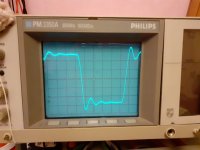
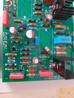
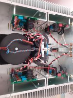
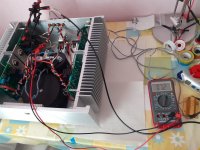
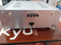
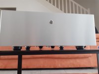
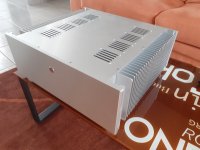
offset level I have -6.8 mv on the right side and -4.3 mv on the left side so I am satisfied.
Here are the latest pictures:


I will write what I did for frequency range measurement:
30 hz - 9.90/9.99v
50 hz - 10.0v
...
5 khz - 10.0v
7 khz - 9.95/10.0
10khz - 9.90/9.99
11khz - 9.90/9.95
15khz - 9.85
20khz - 9.60/9.65
30khz - 9.20/9.25
Perhaps help you 🙂
- I adjusted oscilloscope1khz sinwave for input of amp.(My oscilloscope has wave generator)
- amplificator output adjusted using volume to 10v (measured on oscilloscope)
- I changed frequency and took measurements as,
30 hz - 9.90/9.99v
50 hz - 10.0v
...
5 khz - 10.0v
7 khz - 9.95/10.0
10khz - 9.90/9.99
11khz - 9.90/9.95
15khz - 9.85
20khz - 9.60/9.65
30khz - 9.20/9.25
Perhaps help you 🙂
Looks great! Naim amps live in closed cases, the temperature needs to be constant inside... So maybe better to close the air circulation openings!
I lastly understant that power transistors ft, related with RC, 39p+1k8 feedback value.
for 4mhz (2SC2922) 39p+1k or for 2mhz (MJ15003) 39p+1k8 like that. What is your power trx's ft? Do you think like that?
for 4mhz (2SC2922) 39p+1k or for 2mhz (MJ15003) 39p+1k8 like that. What is your power trx's ft? Do you think like that?
the 2SC2922 is 50Mhz but it hasn't been produced for a while.
The BUV22 is 8 mHz, the Mj15024 is 4mhz
the 2n6341 is 40 MHz
On the resistor you are talking about I saw the following values on the original naim: 1000/1500/1800
it can be noted on the other hand that for the fast transistors (2sc2922 and 2n6341) the values of the resistances in the RC circuits are very different from the other transistors, very low on the 2sc2922 with 27 ohms and 33 ohms
and 1800/2000/2200 ohms on my amp.
I think feedback is related about power trx. But, they don't use 50mhz filter for 2sc2922. I don't know the theory.
"2sc2922 with 27 ohms and 33 ohms". I know, I tested with LTspice and on the circuit, there are no more change. I choosed 150/470. Perhaps, I can try 27/33 again. but, now sound is good enough.
With 3ma idle current on 0.22, there is no crossover distortion.
With 3ma idle current on 0.22, there is no crossover distortion.
I think, feedback rc filter limit the frequency. I saw 1.54mhz (2.2k+47pf NCC series ,MJ15003), 2.27mhz(1k8+39pf also for MJ15003 and some others), 4mhz (1k+39pf 2SC2922) rc filter in that circuit. I wrote before "New naim (NAP100?), 100ohm&100p -> 16mhz..."; I don't know the trx.
I used 1k+39pf for 2sc2922 and 1k8+39p. I feel like 1k+39p better. For 40mhz 2SC2922 trx, 4mhz filter interesting. Also, some manufacturer datasheet says 10mhz for 2SC2922 Hfe.
I said I don't know the theory. If someone write here, it will be super 🙂 For 8mhz trx I would use 39p+1k (and look from the oscilloscope). If I'm not wrong I saw somewhere also 1k2 ohm for the filter (3.4mhz). note that LTspice software doesn't help 🙂
I have not tested this resistor. so I don't know how this changes things under an oscilloscope. if I had not succeeded in stabilizing my amp by playing on the other 4 resistors, I would have tried to vary this one. it could be interesting to test to understand how to play on this value to better adapt other references for the output transistors.
- Home
- Amplifiers
- Solid State
- NAIM NAP250 Original clone build thread