What are you talking exactly ?Maybe add Jeffs comment about ESR of C105/2ß5: 11R typ, 1R7 min!
Ok but the problem is that Jeff young modified the original diagram. Personally I did not detect any oscillation on the regulation board with the capacitors I used and they indeed have a very low ESR (but I could only test at 30 volts and not 56 as in the end device). Likewise on the first two clones that I made they works without worries with very low ESR. I am not a specialist but the Ltspice simulations to my knowledge do not necessarily prefigure what is happening in real life either.
There are so many parameters that can play into the appearance of this type of problem, including routing, perhaps there is a risk of oscillation with low ESRs but which do not necessarily materialize on the finished PCR according to routing? I do not know in any case this last amp works well for the moment. With these new output transistors it is clearly better than my previous ones based on the MJ15003, the highs are better, less aggressive, the upper timbres and there is even a little more detail. Anyway, the work paid off.
There are so many parameters that can play into the appearance of this type of problem, including routing, perhaps there is a risk of oscillation with low ESRs but which do not necessarily materialize on the finished PCR according to routing? I do not know in any case this last amp works well for the moment. With these new output transistors it is clearly better than my previous ones based on the MJ15003, the highs are better, less aggressive, the upper timbres and there is even a little more detail. Anyway, the work paid off.
Interesting! Which version sounds best with wich transistors?
I understood Jeff meant also the original regulator circuit, not only his inverted version. The caps Naim used weren't low ESR ones, were they?
I understood Jeff meant also the original regulator circuit, not only his inverted version. The caps Naim used weren't low ESR ones, were they?
Yes original NAIM use tantale caps with hight ESR on the AMP BOARD but electrolytic Caps on regulator board, but i don't know how many ESR they have.
For the sound it's the new version that sounds better with 2N6341 as output transistors.
For the sound it's the new version that sounds better with 2N6341 as output transistors.
Thank you! Did you also test with and without protection circuit in the amp board? I would be interested to hear about sound quality differences!
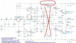
I believe that 🙂 R26,R27& R29,R30 values are changing with output transistors & supply voltage I think. Those resistors related with THD (at least). You can put your circuit Ltspice and measure THD. You can easly find the low THD value. R26,R27 mostly 150&470 for 2sc2922, 560&680 for mj15003. You can write your results here. I'm waiting. Note if HF is not clear change c10&c11. good luck!Thank you! Did you also test with and without protection circuit in the amp board? I would be interested to hear about sound quality differences!
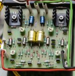
Your amp looks great, very nicely done.
Do you find the rubber pad under the transformer and the cover help with unwanted noise?
Do you find the rubber pad under the transformer and the cover help with unwanted noise?
Thank you! Did you also test with and without protection circuit in the amp board? I would be interested to hear about sound quality differences!
I meant the sound with removed protection like that:
Attachments
hello ! So 12,8 ohms of ESR it's big i'm surprise of that.
For R26,R27 values yes it change with outputs ! but for me it's 150 and 480 for old NAP 250 i see on pics witch use OUTPUTS like BDY58 ?
some NAP use 560 and 680 for R26/27 but i don't know outputs where use
For NAP 140 with 2sc2922 it's very different 27/33/560/390 for 26/27/29/30
i do not do tests for this values but it was interesting to determine best values for each outputs suitable for NAPs
I do a listenning test with and without the protection circuit but with my lab supply on a medium JBL speaker and i do not hear difference.
When i finish my amp i had a channel with and the other without the protection circuit and i see when i turn off the amp the offset stay a long time on the channel without de protection circuit (more than 100 mv more than a minute )
on the channel with the protection circuit the offset stay only few seconds
So i put the protection circuit in place in the two channels because i do not use protection relay for speakers for the moment, i think if a difference exist in the listening quality it's few things.
TY Mulburg i use the rubber pad for vibrations of the transformer
and to pass the output cables of the transformer which come out on the other side
C10 C11 are 470pf By what value do you think they should be changed ?I believe that 🙂 R26,R27& R29,R30 values are changing with output transistors & supply voltage I think. Those resistors related with THD (at least). You can put your circuit Ltspice and measure THD. You can easly find the low THD value. R26,R27 mostly 150&470 for 2sc2922, 560&680 for mj15003. You can write your results here. I'm waiting. Note if HF is not clear change c10&c11. good luck!
Type 🙂 must be Polypropylene PP or POLYSTYRENE PS types. I was used wima PP cap, result was not good. After then, I tried polystrene, it's perfect (original naim's type). And tried PP, standart caps(brown/red film caps), it's as good as PS type.C10 C11 are 470pf By what value do you think they should be changed ?
12,8 ohms of ESR it's big i'm surprise of that.
Yes, you can fit 4R7-10R in series with the cap and use any normal cap. The small caps should be polystrene, otherwise sound might shift. Make sure not to heat them during soldering, i.e. use an alligator clip on the leg as a heatsink...
For MJ15003 (and some other high current transistors, perhaps all fake) I couldn't get satisfied results. For, 2SC2922&40volt. : C4; 47pf (not 39pf), R26,27; 150&470, R29/30; 560&270-310 (not 390), R5; 1K8 (not 1K), R21; 620R, C8;330pf or 220pf (not much important), R14; 1uH&15ohm//, Q9&Q10 MJE243/53 or MJE150030/31 not much difference.Yes, you can fit 4R7-10R in series with the cap and use any normal cap. The small caps should be polystrene, otherwise sound might shift. Make sure not to heat them during soldering, i.e. use an alligator clip on the leg as a heatsink...
Those are for 40volt voltage, 35volt all things must be changed. (1k8, 1k. R26/29, 33/27 ohms ect.)
C4, C8, C9 high voltage ceramics. I coudn't abserved difference with film types.
Test things ,Violine sound not natural means C4 too low or compansation resistors have not good value, distortion in sin wave.
HF not clear, compansation capacitors(470pf's) not good PP or PS type, change type.
All tantal caps, are tantal caps. input tantal has parallel 100nf film capacitor (may be not important).
Bias current 3mv(3.5..) on one 0.22R. Set first and test after hours. There is no vantilation in the box.
Thank you for all these details! I would have to look at that a bit, I'll start by redoing tests on my old NAP 250 clone with my GBF to see what it gives. The problem is that I'm running out of time! I'm pretty busy with my work and I took advantage of my vacation to finish this amp. I saw that mcbride advises to increase the value of the capacity which is in parallel with the ZTX753 in the event of a problem on the HF, what do you think?For MJ15003 (and some other high current transistors, perhaps all fake) I couldn't get satisfied results. For, 2SC2922&40volt. : C4; 47pf (not 39pf), R26,27; 150&470, R29/30; 560&270-310 (not 390), R5; 1K8 (not 1K), R21; 620R, C8;330pf or 220pf (not much important), R14; 1uH&15ohm//, Q9&Q10 MJE243/53 or MJE150030/31 not much difference.
Those are for 40volt voltage, 35volt all things must be changed. (1k8, 1k. R26/29, 33/27 ohms ect.)
C4, C8, C9 high voltage ceramics. I coudn't abserved difference with film types.
Test things ,Violine sound not natural means C4 too low or compansation resistors have not good value, distortion in sin wave.
HF not clear, compansation capacitors(470pf's) not good PP or PS type, change type.
All tantal caps, are tantal caps. input tantal has parallel 100nf film capacitor (may be not important).
Bias current 3mv(3.5..) on one 0.22R. Set first and test after hours. There is no vantilation in
Improving Naim stuff with a nicely laid out PCB design etc.....reminds me of this company in the UK:-
https://avondaleaudio.com/naim-audio-upgrades/
https://avondaleaudio.com/naim-audio-upgrades/
- Home
- Amplifiers
- Solid State
- NAIM NAP250 Original clone build thread