Thanks a lot! But having the power devices on flying leads could alter things quite significantly in my experience. Please keep us informed, I would be specially interested to see the compensation values for your final setup with the power devices connected directly and properly heatsinked, and of course with the original supply voltages!
Interesting part choices BTW! I stick to styrenes for the small values (trying to avoid Wimas in a Naim circuit), and RC55s I didn't like at all in the signal path. RN60 were nice though: you seem to have 4K7 ones in the protection circuit? And are you sure the Oscons are the best choice? Reminds me about Jeffs findings on minimum ESR I referenced earlier. A question: what output resistors did you use: looks like CPF 0.22 3W...? And the black ones?
Last edited:
PSU toroidal 40v simple bridge. I think compansation values related about all circuit, not for only voltage. give your all schematic (all type/values), I can try to test your circuit.
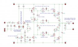
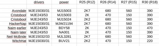
Here is my schematic. As far as I observed MJE243/53s are good for MJ15003 and BYD58, but MJE15030/31s are used by WitchHatAudio to drive BUV21s. I didn't try BUV21s yet, but here they are shown with 150/470 and 220/680 and 2K2. As I have genuine BUV21s from Mouser I would be interested if you could get them run stable driven by MJE243/53s and if so with what values!
Attachments
Last edited:
R26,R27 mostly 150&470 for 2sc2922, 560&680 for mj15003. You can write your results here. I'm waiting.
Here are the values I extracted from various sources so far. Note that the earlier Naim amps with BDY58 sometimes have 1K8, sometimes 2K2 in R25 (R12 on my schematic), so I put 2K in that field (1K8 is also shown in the original NAP90 schematic, but the NAP90 had different output devices as far as I recall). R29 is always 680R. Here is the list:
Attachments
By modifying these values (R25 2200/ R26 680/ R27 560) the problem is solved.
Did you try 2K2/680/560 also with the 15003s?
This is using mj15003. I used BC239C. not BC239B as in diagram. hiiim!
R10 was 620 🙂 r9 may be 390... BC239C and R10 adjust idle current. I used 620 and some like %10 Hfe difference for idle current(<10ma).
Last edited:
No because there is no problem with 2000/470/150Did you try 2K2/680/560 also with the 15003s?
mdardeniz
620 it's the original value of Naim i think
i see you are using other drivers too and other values in the phase compensation for the positive too ! how have you find this values ? just in LTspice simulation ?
classically I only use vishay 3watts metal film resistors for those emitting and output.Interesting part choices BTW! I stick to styrenes for the small values (trying to avoid Wimas in a Naim circuit), and RC55s I didn't like at all in the signal path. RN60 were nice though: you seem to have 4K7 ones in the protection circuit? And are you sure the Oscons are the best choice? Reminds me about Jeffs findings on minimum ESR I referenced earlier. A question: what output resistors did you use: looks like CPF 0.22 3W...? And the black ones?
But since there were no more at mouser at the time of my order, I also ordered coils, these are the ones in black, they are transmitters on my test PCB. on the other hand on my amp they are only put on the output of the amp which gives a slight inductance which is not necessarily worse.
For the ESR of the capacitors I remain perplexed I have not yet seen any problem of instability using low ESR.
Thanks for the information! I will try to carry out my own tests. Some questions about the test setup:
You said you use a 30-40kHz square wave and hook the oscilloscope to the output. I would think this means:
- connect speaker cable to the output of the amp
- connect a load resistor (i.e. 4Ohm / 200W) to the end of the cable
- increase the volume of the square wave so that you get something like 60Vp-p at the output
- check for oscillation on the oscilloscope
Is that correct? I am a bit concerned to get melting leads if testing like that... Also shouldn't we use something more complex than a simple resistor, for example as shown here...?
As for the low ESR caps: I seem to remember comments about problems with stability elsewhere if low ESR caps are used at the output of regulators, maybe even in datasheets...
I use a 6,8 ohms/ 100 W load for the test, only 100 mv signal at intput of the amp, so around 2,9 Volts at output. for a complex load maybe a little speaker by using less strong input signal for my ears ^^ But i think it should works fine on a simple load and i do tests with a capacitor in parallel to test stability.
For the regulator board and the problem with low ESR i can do other tests but you talk about datasheets ? if you have them i would be interesting to look at this.
For the regulator board and the problem with low ESR i can do other tests but you talk about datasheets ? if you have them i would be interesting to look at this.
I don't remember, but maybe it was in regard to discrete regulators, or even in chip regulators. If I find it I will post it!
What capacitor value do you add to the dummy load resistor when testing for stability?
What capacitor value do you add to the dummy load resistor when testing for stability?
i add until 1UF capacitor on a square wave at 10 000 hz it's a stress test for the amp if if the oscillations are well damped then the amp is stable in principle.
I begin with 100 nf then 470nf then 1Uf
i test on 6,8Ohms loads then 4 ohms then 2 ohms to see if the amp remain stable.
I have also already measured the output of the regulation board with the oscilloscope during tests on a square signal. I did not see any particular instability but i don't use capacitance in parallel for check the ragulator stability.
Q1, Q2 and Q3 Hfe, R21 changes the idle voltage at output. I used 620 not 520 and selected proper Q1&Q2's Hfe. Don't look the schematic. I used 520 for LTspice. R29&R30(330 or 390 don't change much) also R26&R27 values are determined looking THD. If there is oscillation, THD was too big. If there is no oscillation I tried to find optimum THD value. For NCC200 THD was around %0.06 (Q1&Q2 have 100ohm resistors). If you look original schematics THD was around %0.02. Those are LTspice values at 1khz. I'm not using regulator circuit. It can change the sound but, I think better speaker will be better than regulator (This is my opinion only).Mdardeniz
620 it's the original value of Naim i think
i see you are using other drivers too and other values in the phase compensation for the positive too ! how have you find this values ? just in LTspice simulation ?
I tested 40khz square wave with oscillocope, there is no oscillation. My final circuit is; (there is one difference I used BC239C not BC239B)
All right ! I tried to look at other photos of the original naims and there are quite a few differents values used for phase compensation but also sometimes in the feedback.
sometimes on the same amplifier a value can be different on each of the channels which makes me say that naim had to measure the phase or the THD on each card to adjust things.
On the other hand, I cannot determine whether there have been NAP 250s using MJ15032 and Mj15033... because I have the impression that certain versions of the 250 use these drivers and not the MJ243/253 suddenly it can also change the values to use.
I'm trying to figure out what makes a different output change the phase is it the frequency? Gain ? the Cob? the linearity ?
I am also trying to understand how to actually measure the phase and determine the phase margin, because i think it's what we have to do to optimise a design.
I do not know how to simulate this in Ltspice and I am wary of simulations because when I tried to use this software I quickly saw that the characteristics entered for the components that can be downloaded from the libraries are fanciful ... clearly you have to enter all the characteristics yourself to get a good simulation, isn't it easier to measure it directly on a prototype ?
They used MJ243/253 (MJ1503X have different pinout BTW), but output drivers changed: BDY56, BDY58, NA001. The values for BDY58 and NA001 are different, and each category shows some variation...
If you can, use MJ243/253 not MJE1500*. LTspice is not final result. Only before oscilloscope and HF measurement (on R15). Only I can say, in my circuit there is no oscillation. Also, I have been interesting about sound quality. if sound was good then, I will solve the oscillation problem/problems (Yes, they are related but this is my way). I tested mostly capacitor and values.
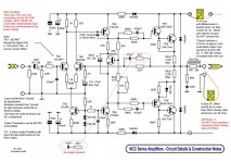
My final circuit is; (there is one difference I used BC239C not BC239B)View attachment 1148133
Cool! May I ask: what hfe do you use with the BC239Cs? And why is your zobel 10R/100n? I saw 8R2/220n on Naim boards with BDY58 and 12R/220n with NA001...
Also why do you have the caps in the compensation networks on the other side of the resistors?
If you can, use MJ243/253 not MJE1500
Can MJ243/253 also drive BUV21s well?
-Hfe are like 640&580.
-Zobel, 10ohm much more usual (related with speaker empedance I beliave). 100nf; I haven't got 220nf. If you got use 220nf.
-compensation R and C are series. doesn't matter which is first or second.
-Nap140's orijinal transistors 2sc2922. I concentrate for it. I think mj243 can drive buv21(fake?). I had big problem with mj243. Perhaps MJ243's were fake or I couldn't find compensation values. there was a oscillation. So I drop it and used mje150**.
- Home
- Amplifiers
- Solid State
- NAIM NAP250 Original clone build thread