Hi olegMy friend
Maybe
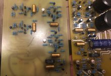
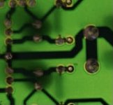
But I not find the connection of 47uf tantalum cap near bias transistor on yours photo
Maybe this one is old photo ?
The temperature compensation transistor next to 47uf is designed below the PCB due to its need to detect the temperature of the heat sink (chassis bottom plate). Currently, most new NAPs adopt this design.
Attachments
Good day
Mr CaoWei
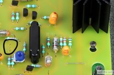
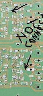
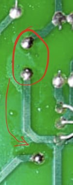
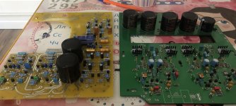
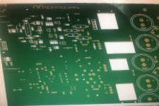
I mean this one
Not have roads on board for connecting parts 🙂)
Mr CaoWei
I mean this one
Not have roads on board for connecting parts 🙂)
Attachments
Last edited:
My friend, you have observed very carefully. The PCB in the picture is the first version (number 20230425), and I only used it for photography. I also made a finished product, but I have never sold this version. I started selling it from the second version (number 20230510), and I guarantee that the second version is very good without any problems.
Attachments


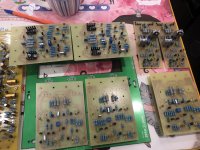
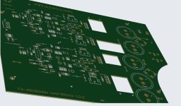
And NAP200 with NAP140 and NAP160 boards
Sizes
Evolution of NAPs
The NAP200 board is not my draw I buy this in market
Sizes
Evolution of NAPs
The NAP200 board is not my draw I buy this in market
Attachments
Last edited:
Guys, you are amazing! Will you upload some gerber files to this thread...? I am interested in all hand drawn Naim boards.
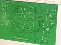
Good dayMy friend, you have observed very carefully. The PCB in the picture is the first version (number 20230425), and I only used it for photography. I also made a finished product, but I have never sold this version. I started selling it from the second version (number 20230510), and I guarantee that the second version is very good without any problems.
Mr Caowei
This design is better than 05.2023?
Last edited by a moderator:
End of design the NAP155XSAnywhere I draw of this model naps too 🙂) for myself from original board
Last edited by a moderator:
Maybe this one but I not sure for quality
https://sl.aliexpress.ru/p?key=a27vUBR
Supplier write about original good parts
https://sl.aliexpress.ru/p?key=a27vUBR
Supplier write about original good parts
I have some PCBs left over from my NAC552 clone project. You can contact me by PM if you are interested.
You mean this one design?

I draw this about one year ago from China
board clone and checking with original 552

Ps. novodel it’s my place slang …
I draw this about one year ago from China
board clone and checking with original 552
Ps. novodel it’s my place slang …
Last edited:
- Home
- Amplifiers
- Solid State
- NAIM NAIT 2 DIY