It's getting pretty obvious.
The blue wire at lower right of your board is from AC plug or power switch.
I think the brown wire that goes to lower right also from AC plug or power switch.
Those theories can be tested with the ohmmeter. This test should be done with power switch on. 0 ohms. It is not unheard of for power cord to get broken, they get stepped on & yanked. If infinity, your problem is outside or power switch.
then one AC blade, blue or brown should go to 0 v on the board.
the other AC blade should go to 240 since you live in UK & use 240.
Any of those solder joints on that board can be bad.
Concur with post 40, you should get about same ohms from two 120 windings. There is a jumper in one to get from 100 to 120. (100 v is Japan, 120 v is western hemisphere or Korea).
Last edited:
BUT you haven't mentioned the impedance of the other 120v winding ?!!!
I measured that previously but I checked again and it's around 10 Ohms.
So what options does that leave us or can we assume it's shorted windings?
It's getting pretty obvious.
The blue wire at lower right of your board is from AC plug or power switch.
I think the brown wire that goes to lower right also from AC plug or power switch.
Those theories can be tested with the ohmmeter. This test should be done with power switch on. 0 ohms. It is not unheard of for power cord to get broken, they get stepped on & yanked. If infinity, your problem is outside or power switch.
then one AC blade, blue or brown should go to 0 v on the board.
the other AC blade should go to 240 since you live in UK & use 240.
Any of those solder joints on that board can be bad.
Concur with post 40, you should get about same ohms from two 120 windings. There is a jumper in one to get from 100 to 120. (100 v is Japan, 120 v is western hemisphere or Korea).
I have 240V AC coming into the receiver and the power switch is functioning correctly. This AC input is connected on the small board via the power switch to the RED and BLACK wires that run inside the transformer. As mentioned previously, the metal cover on the transformer has been spot welded making access impossible? You mention a jumper and someone else mentioned a possible thermal fuse but no doubt they are under that metal cover?
I may reflow all those joints on the small board just to rule those out?
Last edited:
I measured that previously but I checked again and it's around 10 Ohms.
So what options does that leave us or can we assume it's shorted windings??
Why on earth would it be shorted windings ?!
If it was shorted windings , fuses would be blowing.
Two 120v primary’s, each should have ~8ohm across ‘em at DC
As there’s no standby TX in this product, that ~16ohm should also be present at the mains plug
If you can’t see the 16ohm at the plug, there’s a break somewhere between that and the TX, be it a dodgy cable/connection or fuse that you haven’t spotted yet.
PS: the jumper is just on the square PCB , this just puts both 120v windings in series for 240 operation.
The internal thermal fuse (if indeed there is one) would show up on your two ~8.2ohm checks
Last edited:
Primary coil is 120-0-120, is it not, with possibly a 100V (Japan) tapping on one coil.
Start from there.
Start from there.
Okay,
A little pondering and looking back at previous statements lets re-cap.
You have 245 volts AC at the Red and Black wires entering the transformer?
You measure approximately 10Ω across each section marked 0 - 120 on the brown board (White /Brown and Yellow/Brown wires.)? So with the amp unplugged and if everything was working normally, you should measure approximately 20Ω across the red and black wires, but yours is O/C.
If the answers are yes, you have 240 volts into the transformer and both primary windings are correct, then you have to conclude there is another fuse or lost connection inside the transformer.
Further - Have a look at the service guide. There are 6 wires entering the transformer on the primary side. There are only 5 taps on the windings.
That strongly suggests that either the Live or Neutral entering the transformer (on the Red and Black wires) has a fused connection internally that has failed...
Attachments
Hi Alan and thanks for your re-cap of this ongoing saga!
Your summary of my measurements and readings is correct I would confirm that there are no other connections, components or circuitry between the AC mains and the BLACK/RED wires going into the transformer apart from the fore-mentioned on/off switch and the small board. So no other fuses that I can see?
To eliminate the mains power lead, the on/off switch and the small board I am considering disconnecting the BLACK and RED wires and connecting them directly to a new power lead - so a direct connection from the AC mains to the transformer.
Is that advisable if implemented with the usual safety precautions or will something go bang?
After that I may look at trying to remove the spot welded metal cover on the transformer - the welds should pop - to access the Primary and Secondary connection points?
Last edited:
Before you do that (it won't go bang if you do, but use the lamp limiter) - out with the meter again please.
Unplugged of course, measure the resistance from the Black wire/pad to any of the other pads other than red. If you have continuity then do the same from the Red wire/pad to any of the other pads other than black.
If either is open circuit then there is an internal fuse or break in that lead inside the transformer, so no point trying a direct mains connection.
I'm not sure popping the cover will get you any where if there is a thermal fuse in there. It will not be replaceable, but you could prove what the problem is.
Thanks Alan - I think we've reached a conclusion?
Measuring the resistance from the Black wire/pad to any of the other pads other than red I'm getting nothing.
Doing the same from the Red wire/pad to any of the other pads other than black I'm getting a low Ohms reading.
Same pattern when checking continuity - nothing for Black wire, continuity for Red wire.
The statement that AC comes in on red & black doesn't make sense to me. Red should go to the transformer. On the picture there are not two wires to the terminals labeled red & nothing (black)
The black wire doesn't have a name in post 31. Is it possible the black is the earth wire, to the case? In that case it should connect to nothing else but the safety ground of your power cord.
Low side of AC cord should to to 0 on little board. Also one wire of transformer. 120 next to it should go through a wire to transformer, also through jumper (soldered to board labeled 220-240) to 0 above. 0 above should go to transformer. 120 above should go to the transformer, also the other side of the AC cord, or the power switch.
If there is low ohms (6 to 10 you say) between 0 and 120 below, and between 0 and 120 above, the transformer is not open.
You haven't said where blue goes. Looks like a power cord. There is a terminal labeled grey, which goes to nothing. Looks like a good place to put the other power cord or AC switch wire, which should then go to 0 or the top 120.
Last edited:
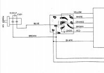
If you look again at the picture in my Post #29 above you should see the AC mains cable coming in at the bottom right area - BLUE and BROWN wires going the two terminals there.
The BLACK wire that runs to the transformer is connected to the AC mains BROWN wire
.
There are two other BROWN and BLUE wires that run to the on/off switch - they both run off the bottom of the picture. This BLUE wire is connected to the AC mains BLUE wire while the BROWN wire connects to the RED wire that runs to the transformer - this can just be seen at the top right off the picture just behind the YELLOW wire.
Accordingly, the RED and BLACK wires that run to the transformer carry the AC mains at 245V AC.
Hopefully this clarifies matters but it takes us no further forward as the receiver still doesn't work!
On the basis that I've nothing to lose I've popped off the metal cover and will have a go at exploratory surgery tomorrow.
I fully appreciate that this is a one-way street and that I probably won't find the fault or be able to reassemble the transformer. I'm doing it for my own entertainment and education and will post some pictures if people are interested?
I fully appreciate that this is a one-way street and that I probably won't find the fault or be able to reassemble the transformer. I'm doing it for my own entertainment and education and will post some pictures if people are interested?
Okay that explanation of power cord makes sense. Blue & brown, yes that could be right.
I won't need pictures, been there, done that. I can't repair EI transformers, except maybe if the studs are loose & the laminations hum. My rewound secondary was smaller than original since copper instead of aluminum, and I still couldn't make it fit or keep it from shorting to the laminations.
There are way too many output voltages from this transformer to replace. That goofy impedance switch is a cheapskate way to get away with $3 heatsinks on the output transistors. Maybe sell off the boards for parts or repair, some people will buy anything.
I'd scan gumtree & ebay for something easier to fix. I picked up a PV-4c for $15 last month, +80 freight from AZ. Banana jack broken off, flange bent from dumpster trip, dirty inside as the inside of a vacuum cleaner. Transformers didn't stink. Freight shouldn't be that high in UK. Nice simple 120 w/ch 8 ohm, 200 w/ch 4 ohm. I fixed the PV-4c that was stolen 9/20 for $80, new output transistors, rail caps & a dozen little electrolytic caps. That one cost me $20 + $20 freight from the next state.
Got a PV8 mixer for $40 +$25 freight, only thing wrong was wall transformer was missing. Replacement $3 @ charity resale shop. (12 vac instead of 16 vac, but works for signals <10 v)
I just have to be patient, sometimes there is no amp under $200, like this week. Crowns & QSC's are also easy to get schematics for, beside Peavey.
Waited 18 months to replace my $300 each SP2-XT speakers stolen, freight from Massachusetts would be $1000. Then a pair of SP2(2004) came up 120 miles away for $400, $600 each new. Guy wanted a new guitar, NOW! They just barely fit in the wife's Hyundai Elanta.
Happy repairing.
Last edited:
I've taken the non-destructive disassembly of the transformer as far as I can and there is no evidence of any fault! There may be an internal fuse or break in one of the leads inside the transformer but I can't find it? Any further disassembly would have to be destructive and there seems little point in proceeding further.
Thanks to everyone for their helpful contributions
Time for a change of direction - is there a WANTED section on this Forum on the off-chance that someone may have a transformer for a NAD 7020i? Worth a shout ... ?
Thanks to everyone for their helpful contributions
Time for a change of direction - is there a WANTED section on this Forum on the off-chance that someone may have a transformer for a NAD 7020i? Worth a shout ... ?
I suspect very little chance of a replacement, but worth a try at least.
Left hand side, 'Comercial Sector' then 'Swap Meet'.
WTB = Want To Buy.
Good luck, Alan
Left hand side, 'Comercial Sector' then 'Swap Meet'.
WTB = Want To Buy.
Good luck, Alan
Thanks Alan - worth a punt but after that it's up for sale for parts!
https://www.diyaudio.com/forums/swap-meet/377430-wtb-power-transformer-nad-7020i.html#post6795702
https://www.diyaudio.com/forums/swap-meet/377430-wtb-power-transformer-nad-7020i.html#post6795702
I've tracked down someone who says that he can reverse engineer the existing transformer and rewind on a more modern core.
He does, however, need to know the voltages on all those Secondaries - can anyone help me decipher the NAD schematics?
He does, however, need to know the voltages on all those Secondaries - can anyone help me decipher the NAD schematics?
Reverse engineering is just that.
Take apart what you have turn by turn and section by section. Then you actually do not need to know the secondary voltages. Just a tedious operation.
To build a replacement without taking the original apart you do need to know the secondary voltages. There are no AC voltages on the NAD circuits I have access to, but once removed from the amp you could try powering the transformer bypassing the 'fused' line and measuring the secondary voltages.
Finally - Have you considered there is a fault on the amplifier that has caused this problem?
Thanks Alan for your ongoing support and interest.
You mentioned 'powering the transformer bypassing the 'fused' line and measuring the secondary voltages' - any advice on how I could do that?
And of course at the back of my mind is that there may be a fault with the receiver which has caused this problem - but that's a bit 'chicken and egg'?
You mentioned 'powering the transformer bypassing the 'fused' line and measuring the secondary voltages' - any advice on how I could do that?
And of course at the back of my mind is that there may be a fault with the receiver which has caused this problem - but that's a bit 'chicken and egg'?
The NAD 7020i power page schematic I have, there is no primary fuse or circuit breaker. There are fuses on most secondary windings, but not on +5.6 v & +12 v windings. Thus NAD has set this receiver up to burn transformers fuse if an electrolytic cap in that section or something else shorts in the tuner. Great way to sell transformers, if the company was still operating.Finally - Have you considered there is a fault on the amplifier that has caused this problem?
- Home
- Amplifiers
- Power Supplies
- NAD 7020i - DOA