Plug in the AC cord and switch the power on.
Stop at the first place that has no AC voltage, in this order:
Check for AC line voltage before the power switch.
Check for AC line voltage after the power switch.
Then on the secondary wires, before the impedance switch.
Then just after the impedance switch.
Then just after both secondary fuses.
These AC voltages are all floating measurements, between two "hot" nodes.
For example, the last AC measurement above is between the ends of C503.
No probes go to ground until you are measuring DC voltages.
Thanks rayma - as mentioned above I have around 245V AC either side of the power switch but no Secondary AC whatsoever at the Impedance Switch contacts?
Similarly there is no AC across F503 or F504?
What's confusing me are the multiple Primary inputs to the transformer (six in total) and the multiple Secondary outputs (twelve in total). Although all Primary input voltages are coming off the AC mains via that small board adjacent to the transformer, there are no Secondary AC output voltages that I can find??
Last edited:
Thanks rayma - as mentioned above I have around 245V AC either side of the power switch but no Secondary AC whatsoever at the Impedance Switch contacts?
Similarly there is no AC across F503 or F504?
What's confusing me are the multiple Primary inputs to the transformer (six in total) and the multiple Secondary outputs (twelve in total). Although all Primary input voltages are coming off the AC mains via that small board adjacent to the transformer, there are no Secondary AC output voltages that I can find??
Positively ID the primary connections at the TX (looking for that 245VAC) with the power on and switched on, i.e. trace it nearer to the TX.
Then pull the power and measure primary impedence at the same point. if nothing there you simply have a duff TX (O/C primary)
Firstly it's thanks to indianajo for the reminders concerning safety but you can be assured that all appropriate procedures are being followed. You can never state these points too often!
I would also agree that a shorted transformer would have that distinctive smell we are all familiar with but not so in this case?
The impedance Switch is on the Secondary side of the transformer and there are no AC voltages on any of the switch connections.
Thanks also to MikePP - I identified the brown and white wires shown at the top left of the image below and after pulling the power I am reading 10 Ohms across those connections. This image shows the multiple Primary and Secondary wires associated with the transformer:-

And here is a picture of the small board next to the transformer which connects the AC mains input to the on/off switch and Primary inputs. I still have some concerns about this board and whether or not it is functioning correctly:-

Finally, for now, I don't see any way of checking the physical Primary and Secondary connections as the metal cover has been spot welded:-

I would also agree that a shorted transformer would have that distinctive smell we are all familiar with but not so in this case?
The impedance Switch is on the Secondary side of the transformer and there are no AC voltages on any of the switch connections.
Thanks also to MikePP - I identified the brown and white wires shown at the top left of the image below and after pulling the power I am reading 10 Ohms across those connections. This image shows the multiple Primary and Secondary wires associated with the transformer:-
And here is a picture of the small board next to the transformer which connects the AC mains input to the on/off switch and Primary inputs. I still have some concerns about this board and whether or not it is functioning correctly:-
Finally, for now, I don't see any way of checking the physical Primary and Secondary connections as the metal cover has been spot welded:-
10R DC primary impedance is fine for this sort of amp.
If this was def where you saw the 240VAC then you should have secondary voltages.
If this was def where you saw the 240VAC then you should have secondary voltages.
I've just spotted your confusion with why so many (apparent) primary connections ........
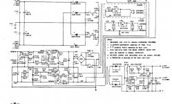
Here is the 7020i TX area and I missed it at first there are secondary taps shown on the primary side in the circuit diag.... NAD aren't known for their clairity on some service manuals 🙄😀
So you should have probably six (apparently) on the primary side (with a 220/240 variant of this amp, and five (apparently) on a 120V version.
220/240 version - 0v tap,220 tap,240 tap and the secondaries for 5v6 (tuner) and 12v2 (tuner) and the associated 0v tap.
120 version - 0v tap and 120v tap and the secondaries for 5v6 (tuner) and 12v2 (tuner) and the associated 0v tap.
Then (apparently) on the secondary side , you'll have eight ?.. 2 main rails wuth a 8ohm/4ohm tap on both. and 3 that feed bridge D511 for preamp supplies.
(I only say apparently because NAD didn't put them on the circ diag all the conventional secondary side)
Attachments
Last edited:
Thanks MikePP but this all getting even more confusing!
I checked the connections on that small board again and can confirm that the incoming AC mains is connected to the RED and BLACK wires that run to the transformer via the on/off switch. I measured 245V AC across these connections but when I powered off there was NO reading (as opposed to a ZERO reading) on the Ohms setting of my DMM?
I checked the connections on that small board again and can confirm that the incoming AC mains is connected to the RED and BLACK wires that run to the transformer via the on/off switch. I measured 245V AC across these connections but when I powered off there was NO reading (as opposed to a ZERO reading) on the Ohms setting of my DMM?
I often have to double and triple and quadruple check when I’m presented with a O/C primary TX Just to be absolutely certain you’re measuring at the correct point
Circ doesn’t show a thermal fuse on the primary and they usually do, but anything’s possible
Circ doesn’t show a thermal fuse on the primary and they usually do, but anything’s possible
I agree with you MikePP - I have years of experience of measuring and checking but I seem to be having a Senior Moment/Meltdown with this receiver to the point that my confidence has gone and I've regressed to asking basic questions!
The AC mains input is connected to the transformer Primary via the small board I have referred to previously - here's a picture of the opposite side:-

I've now carefully traced all wires and connections and can confirm that only the RED and BLACK wires going to the transformer appear to have AC voltage - I'm measuring 245V AC across these. The other four wires (WHITE, BROWN, YELLOW and ORANGE) don't seem to be doing anything and don't seem to have any AC voltage?
But am I measuring at the correct points as I note the confusing annotations on the board?
There is also no evidence of a thermal fuse anywhere but I agree that anything is possible with this receiver?
The AC mains input is connected to the transformer Primary via the small board I have referred to previously - here's a picture of the opposite side:-
I've now carefully traced all wires and connections and can confirm that only the RED and BLACK wires going to the transformer appear to have AC voltage - I'm measuring 245V AC across these. The other four wires (WHITE, BROWN, YELLOW and ORANGE) don't seem to be doing anything and don't seem to have any AC voltage?
But am I measuring at the correct points as I note the confusing annotations on the board?
There is also no evidence of a thermal fuse anywhere but I agree that anything is possible with this receiver?
Any thermal fuse would be inside the TX
What I’d do next is confirm impedance of all five of the primary cables there
You’ve got a multi-voltage variant not shown in the circ dish
Two 120v windings (which obvs should be identical)
One of which has a 100v tap (which will be a little less than the 120 winding impedance)
So the TX is able to be set up for all country’s:
100v, 110, 220 and finally 240
If you’re in a 240v country , the top 120 will be linked to 0 in the row below, and the 240 will be fed from top left to bottom right to make up the full 240
Oh dear!
Thanks MikePP but you're definitely starting to lose me! 😕
The image below shows both sides of the small board and I am really struggling to trace the connections across this board and to the transformer:-

Perhaps I'll try and number them to see if that helps?
Thanks MikePP but you're definitely starting to lose me! 😕
The image below shows both sides of the small board and I am really struggling to trace the connections across this board and to the transformer:-
Perhaps I'll try and number them to see if that helps?
Last edited:
I’m doing this on a phone, with bad reception and I can’t annotate on my phone easily.
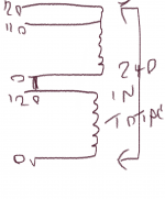
In the last photo , there are two connections at top of board, 0 and 120
Then below that three more connections
0, 110 and 120
And a link between 120 (top row) and 0 (the row below)
Agreed ?
So in a 240V country the N comes in at 0v (top row), flows through that 120 winding, then is connected to 0v on 2nd row via the link you can see, flows right through that 2nd winding to the 120v point where the L is connected
(It’s a world wide transformer being capable of being set up for every country on the planet)
Thanks for that MikePP.
I've tried to follow your logic and have annotated the back of the board accordingly - hope I've got it right:-

And now the crucial question - where do I connect my DMM probes?
I've tried to follow your logic and have annotated the back of the board accordingly - hope I've got it right:-
And now the crucial question - where do I connect my DMM probes?
Oh dear. All very confusing.
Not sure I have read everyone's input, but a couple of things are nagging me.
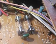
First is are the fuses really okay. Looking at the picture one does not look good - is it blown?
Second is it is easy to check if the primary is whole (not OC). Put your meter on 1000Ω range, put a lead on each prong of the mains plug and press the on switch. If you get a resistance reading the transformer is probably fine. If not leave one probe on the neutral pin and follow the live wires back until you find a break.
Not sure I have read everyone's input, but a couple of things are nagging me.
First is are the fuses really okay. Looking at the picture one does not look good - is it blown?
Second is it is easy to check if the primary is whole (not OC). Put your meter on 1000Ω range, put a lead on each prong of the mains plug and press the on switch. If you get a resistance reading the transformer is probably fine. If not leave one probe on the neutral pin and follow the live wires back until you find a break.
Attachments
Similarly there is no AC across F503 or F504?
Still sounds like a misunderstanding. You measure the AC voltage between the two fuses,
at the same point on each (either before or after). One probe on the upper fuse,
and the other probe on the lower fuse. No ground connection. No measurement across
the two terminals of a single fuse, that will be zero volts, a short circuit.
Last edited:
Yeah 🙂
Even go right back to the plug across L and N and measure for the low resistance (sub 50ohms) as you switch it on and off
If it’s not there at the plug prongs but present at the TX then there’s clearly a break somewhere
Some amps have fuses obscured by cables or guards etc
What’s to mark up/annotate ?, it’s clearly already marked up on the screen print, where each is soldered
Two 120v primary windings , one being slightly different with a 110 tap too
Even go right back to the plug across L and N and measure for the low resistance (sub 50ohms) as you switch it on and off
If it’s not there at the plug prongs but present at the TX then there’s clearly a break somewhere
Some amps have fuses obscured by cables or guards etc
I've tried to follow your logic and have annotated the back of the board accordingly
What’s to mark up/annotate ?, it’s clearly already marked up on the screen print, where each is soldered
Two 120v primary windings , one being slightly different with a 110 tap too
I would expect 0-120-220-240 on the primary coil
And the rest on the secondary coils, that may be clearer.
Check for continuity on all the tappings as marked.
If OK...then:
Use a direct dim bulb tester to primary, after disconnecting the switches, or connecting past them.
If all goes well, check the secondary outputs.
And the rest on the secondary coils, that may be clearer.
Check for continuity on all the tappings as marked.
If OK...then:
Use a direct dim bulb tester to primary, after disconnecting the switches, or connecting past them.
If all goes well, check the secondary outputs.
As anticipated, I tested all the Primary connections on the small board and there is no AC present anywhere apart from the AC mains input!
Went back a step and connected my DMM across the L & N plug terminals looking for anything on the Ohms range - again nothing?
Checking across the 120V tap on the small board I'm getting 8.6 Ohms and across the 100V tap I'm getting 7.2 Ohms - all very strange?
All the fuses were rechecked and are showing continuity and a low Ohms rating.
Not much more I can try?
Checking across the 120V tap on the small board I'm getting 8.6 Ohms and across the 100V tap I'm getting 7.2 Ohms - all very strange?
All the fuses were rechecked and are showing continuity and a low Ohms rating.
Not much more I can try?
I'd expect a 7.2ohm across the 100v winding and slightly more across the whole 120v winding (i.e. 8.6ohms)........
BUT you haven't mentioned the impedance of the other 120v winding ?!!?
😱
Which should be about the same at 8.6ohms, if that's O/C then you won't have anything at the mains plug, because as I've said these two 120v windings are in series to work on 240vac
Last edited:
- Home
- Amplifiers
- Power Supplies
- NAD 7020i - DOA