This is where I am not understanding you.
If you have no DC offset on the output (you say a millivolt or so after 10 minutes) and yet you have -31v on Q609 then something is very wrong because those figures imply -31v across the two PNP transistor base emitter junctions.
So you need to look where that volt drop is happening. Is the print open circuit? or is one of the transistors open circuit?
Voltage measurements will show where the problem is.
Attachments

this is where i was going to start so once i start testing later in the week ill give you an update 🙂
Following this repair thread and Mooly's advice with curiosity 🙂
In the schematics I see that NAD used the venerable and not always well-reputed 2N3055 as NPN output device! As we discussed in another thread in May, Kenwood suggested them as possible substitutes in their 1960's TK-400 amps and TK-80U receivers as well.
Good luck, poundy, all will work out well. Feels like a shot output, but that feeling needs to be confirmed (or corrected) by measurements 🙂
ok so im starting to look at this tonight as my curiosity is getting the better of me
outputs only(centres)
R= RIGHT CHANNEL
L-LEFT CHANNEL
MO=main only speaker switch position only
RO= remote only speaker switch position only
both=both
Speaker switch position
RM 2mv OFF
LM 7m OFF
RR 2mv OFF
LR 8mv OFF
RM 49mv MO
LM 21v MO
RR 2mv MO
LR 8mv MO
RM 2mv RO
LM 8mv RO
RR 49ma RO
LR 21v RO
RM 49mv both
LM 21v both
RR 49ma both
LR 21v both
bit of an odd one this, so new to me.
Last edited:
I'm not 100% sure what you are measuring here 🙂 Is this the voltage as seen on the output transistor emitters, in other words on the main output line?
Its very confusing to follow really without being there and seeing what you are doing.
The speaker selector switch should not influence the amplifier output at all when no load is connected.
The ma readings are really mv... yes.
Are you saying that the switch setting is making the amplifier output rise to 21 volts?
If so then that would only make sense if the wiring to the switch was altered and wrong in some way... can't really see anything else.
It will tomorrow when I look in again, its been a busy day.
oh its my typing and stupid brain.
yes of course mv not ma
all measurements are from the speaker terminals and yes they do change when you alter the switch postion
sorry i thought it would be easy to follow, i was only just reporting what i found as being a bit odd thats all.
im working my way through it so i let you know what i find, and i know what you mean about the long day bit, so no worries
The NAD diagrams I have don't seem to show a version with a speaker selector switch. They just have a single speaker output switched via the headphone socket.
Fault find by measuring on the main speaker output line direct on the amp PCB, not from the speaker sockets. Something could be wrong from the PCB to the sockets via 'the switch'.
Fault find by measuring on the main speaker output line direct on the amp PCB, not from the speaker sockets. Something could be wrong from the PCB to the sockets via 'the switch'.
ive put this away for now as its a side project for myself, but here is the diagram in case you need it any other time
i did work on this quite late last night and its not an easy beast to work on.Very 'crammed in' and realy heavy, but i did test some of the transistors and found C614 to be faulty.It didnt realy change anything and im not getting any current draw on the lamp tester.
quite odd realy.The centre voltage is fine if you have it on the main speaker switch setting only,its on the remote ones so it think it is further back, and not just one fault.
The left power meter on the front panel is showing a slight output once settled so something is going on, but ill find it.🙂
Attachments
Begin with some old fashioned basic tests.
1/ Is the speaker fuse intact? Don't laugh, you have to check it.
2/ Measure the voltage from chassis ground to the speaker fuse. You should see just the DC offset of the amp. This point should be unchanging as you alter the speaker selector switch.
1/ Is the speaker fuse intact? Don't laugh, you have to check it.
2/ Measure the voltage from chassis ground to the speaker fuse. You should see just the DC offset of the amp. This point should be unchanging as you alter the speaker selector switch.
OK. See what you find by measuring first to the the main output (at the fuse) and assuming that measurement is OK then you work toward the sockets.

That is somewhat strange then.
Ideally the next step would be a scope check to see if the amp was unstable and whether that instability was generating a signal that the meter was then registering. Such instability is usually at very high frequency.
If you remove C802 (for the left channel) then that removes the signal to the meter drive amplifier. If the meter now reads zero then it looks like the amp is unstable.
That is somewhat strange then.
Ideally the next step would be a scope check to see if the amp was unstable and whether that instability was generating a signal that the meter was then registering. Such instability is usually at very high frequency.
If you remove C802 (for the left channel) then that removes the signal to the meter drive amplifier. If the meter now reads zero then it looks like the amp is unstable.
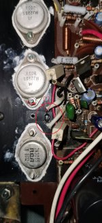
is there a way to test the package diodes.They are attached to the heatsink which is strange i thought.(see attached photo)
there is quite alot going in with this amp.Ive been testing the transistors, and replaced a few components as they were either burned out or looked like it.the board is covered in the glue use to secure the main filter caps so ive had a hell of a job identifying the parts, but ive managed to get most of it off without loosing the marking detail which is good.at one point the centre was back to 20mv but now its back to 21v, so there are proberbly some dodgy joints here as well as anything else.Alot of the poly caps look quite dark,not black but look like they ahve god hot-are these likely to be ok? should i take out and test? i dont normely remove these unless i need to.
Attachments
The poly caps are almost certainly OK, the black is from the heat of the resistors causing discolouration/contamination like you get on a white wall behind a radiator.
The diode packs can be tested up to a point but it won't tell you if they are intermittent (unless it actual fails while testing).
They should read open circuit one way around but the other way around with a four diode package is to many to read on most meters on the diode range.
Remember the meter measures the voltage at the probes when you diode test and so four diodes generates around 2.5 volts drop which might be outside what a particular meter can read on diode test range.
So you do it the old fashioned way and measure the voltage across them under a known test condition by passing a fixed current through them.
9 volt battery and series resistor to limit current. 9 volts less 2.5 volts is 6.5 volts. Lets test at say 2 milliamps. So you need a 6.5/0.002 value resistor. Use the nearest value you have. You can safely go up to about 10 milliamps I would think so you can test at different currents.
I'll let you work that one out 🙂
The diode pack won't give you a high DC offset with no other problems, if the diodes fail open you would get massive current flow in the output transistors and drivers. Destructively high current.
when im testing componets that are grounded im getting 1.7mv, not 0v is this ok ,ive not had this before, and they all seem to be the same.
If you mean measuring voltages from ground to a part that should also be grounded then yes, its normal because of current flow in conductors generating small volt drops.
Every wire, every bit of print, they all generate a volt drop across them when current flows.
Every wire, every bit of print, they all generate a volt drop across them when current flows.
- Home
- Amplifiers
- Solid State
- NAD 3030 in a mess