Maybe a good picture of the resistors on the board similar to the one Goldie posted might help us see what is actually fitted.
Does your board look similar to Goldies picture?
78 ohm does not sound like a valid value tbh and in any case would be far to low a value for its intended use here.
What is the meter you are using? Make and model?
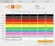
A white/red/black resistor would be 9, then 2 and then 0 (no) multiplier giving 92 ohm.
We need to be sure you are getting correct results from your meter. Any resistors you have should all be giving the correct value on any of the meters you have.
Does your board look similar to Goldies picture?
78 ohm does not sound like a valid value tbh and in any case would be far to low a value for its intended use here.
What is the meter you are using? Make and model?
A white/red/black resistor would be 9, then 2 and then 0 (no) multiplier giving 92 ohm.
We need to be sure you are getting correct results from your meter. Any resistors you have should all be giving the correct value on any of the meters you have.
Attachments
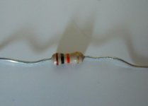
The board looks identical to Goldie's except the two resistors in question the R547 and the R548. They are red green then gold on mine.
The meter is called a Smart Digital Multimeter. CEM and then DT -936.
I have a resistor here that shows 98.2 k ohm on the meter. That's 98000 isn't it?
The color code is red, black, yellow, gold.
The meter is called a Smart Digital Multimeter. CEM and then DT -936.
I have a resistor here that shows 98.2 k ohm on the meter. That's 98000 isn't it?
The color code is red, black, yellow, gold.
Red, black and yellow should be 200K. Are you touching the meter probes as you measure? Your body has measurable resistance that will affect the reading if you touch the probes.
The board looks identical to Goldie's except the two resistors in question the R547 and the R548. They are red green then gold on mine.
The meter is called a Smart Digital Multimeter. CEM and then DT -936.
I have a resistor here that shows 98.2 k ohm on the meter. That's 98000 isn't it?
The color code is red, black, yellow, gold.
98.2k is 98,200 ohms but that does not tally with the colours of red, black and yellow which as Bill says is 200k.
I'm puzzled on these resistors of yours.
Put the resistor on a table and press the probes onto the leads but don't touch the connections. See if that makes a difference.
Back to your amp...
As to your resistor of red, black and yellow. If you connect that across R548 do you get sound? Yes or no 🙂
If no then do you get sound if you snip (disconnect) the white wire to the switch? Yes or no.
Attachments

Last edited:
Bill... I hadn't consciously read your thoughts on body resistance... it was the first thing I thought of when I read his post. Maybe I saw it and it didn't register 🙂
Sorry, I blew the color on it. It's actually brown black and yellow. The brown is light, easy to mistake it for red or some other color. The resistor is tiny and the colors fade in the plastic bag. I used alligator clips on the resistor so I wouldn't touch it. And actually it's not 98.2 k but 9.82 k. Sorry again. I have not put it across the R547 or 548 but I've tried a few other resistors and the sound was on. Also, most of the resistors I have are low values so if I have to change the R547 or548 I'll have to first buy new ones
Brown, black, and yellow would be 100K so measuring 98.2K would be possible...9.82K not so much.
I have not put it across the R547 or 548 but I've tried a few other resistors and the sound was on.
We're covering a lot of ground with this aren't we 🙂
If the switch is leaky (if... and we don't know yet) then putting a lower value resistor across R547 may well work because the low value 'overrides' the leak if that makes sense.
We're getting there...
One aspect to check whether or not the decoupling arm to earth of the feedback divider network is continuous for a.c. purposes. If there is a bad connection to earth or a leaky capacitor in that arm the closed loop gain of the stage will tend to reduce to one.
I am trying to send a picture of the resistors of this amp, not sure if it gets thru.
As for tests, putting a low resistance resistor like 1 k ohm across either R547 or R548 the sound is on. Anything higher than 20 or like that 98.2 or 100 k ohm, no sound.
White wire disconnected, sound is on.
Hope this helps a little.
Peter
As for tests, putting a low resistance resistor like 1 k ohm across either R547 or R548 the sound is on. Anything higher than 20 or like that 98.2 or 100 k ohm, no sound.
White wire disconnected, sound is on.
Hope this helps a little.
Peter
Attachments

I think that helps a lot Peter. Your resistors are both 150k in that picture.
Based on what you describe... this is where it gets interesting... and the switch would appear to be leaky.
The switch should be 'open' for the circuit to work (unmuted) and so if connecting that lead causes the circuit to mute then it implies the switch is passing current.
Can you confirm that with the wire disconnected that you now have around positive 15v or so on the diode D507.
I'm just about to go out but a quick check on the switch would be to measure the resistance between the two wires. The white must remain disconnected for that and also make sure the amp is OFF. You are reading across the contacts of the switch.
It should read open circuit (as if there is nothing there). If you get a resistance reading then the switch is faulty.
It should read open circuit (as if there is nothing there). If you get a resistance reading then the switch is faulty.
Yes, it's positive 13 volts on the diode.
not sure on the resistance. Amp off, white wire disconnected then black probe connected to ground with red probe touching the white and after that the red connector on the switch?
not sure on the resistance. Amp off, white wire disconnected then black probe connected to ground with red probe touching the white and after that the red connector on the switch?
Peter - the +13V on D507, with the white wire disconnected, is good.
To measure the switch resistance - firstly, the amp has to be off (safest is unplug it from the mains, as you're measuring very close to the main power connections), and the meter set to read resistance.
I'm not sure where you disconnected the white wire, at the pcb end, or at the switch itself ? From your description - I'm thinking you desoldered the white wire from the switch ? (pls. say if not). If that is the case, then you just need to put one meter probe onto the switch terminal where you desoldered the white wire from, and the other meter probe onto the switch terminal where the red wire is still soldered to it. The meter will then show either an open circuit, or a resistance value.
Still with the amp disconnected from the mains supply, you can now press the on/off button once, and repeat the same switch measurement.
Those 2 measurements on the switch will show if it is 'leaky', and the cause of the problem.
Yes, I've desoldered the white wire.
The amp off plug pulled I get 62 ohms on the meter set in the ohm range.
The amp on, the switch pushed on that is, plug still out the meter shows OL
The red probe was connected to where the red wire is connected on the switch and the black probe where the white wire was connected in both instances
The amp off plug pulled I get 62 ohms on the meter set in the ohm range.
The amp on, the switch pushed on that is, plug still out the meter shows OL
The red probe was connected to where the red wire is connected on the switch and the black probe where the white wire was connected in both instances
Again, not as expected:
Amp OFF, plug pulled, and the 2 meter leads touching the 2 switch terminals where red & white are usually connected, I would expect almost no resistance, e.g., something like 0.1 Ohms (I'm measuring a spare switch here). You're measuring 62 Ohms - suggesting the contacts are possibly 'dirty', I can't see where else 62 Ohms could be coming from. Is the 62 Ohms repeatable ?
Amp ON, plug pulled, and the 2 meter leads in the same places, I would expect OL for a good switch, as indeed you're measuring.
Need to have a think here... try the following:

The photo shows the 'normal' positions of the red and white wires on the switch where the yellow lines indicate - yes ? please confirm (important).
If so, please repeat the same measurements as above, but putting the 2 meter leads onto the 2 unused terminals indicated by the orange lines and marked NEW. What are the values then ?
Amp OFF, plug pulled, and the 2 meter leads touching the 2 switch terminals where red & white are usually connected, I would expect almost no resistance, e.g., something like 0.1 Ohms (I'm measuring a spare switch here). You're measuring 62 Ohms - suggesting the contacts are possibly 'dirty', I can't see where else 62 Ohms could be coming from. Is the 62 Ohms repeatable ?
Amp ON, plug pulled, and the 2 meter leads in the same places, I would expect OL for a good switch, as indeed you're measuring.
Need to have a think here... try the following:
The photo shows the 'normal' positions of the red and white wires on the switch where the yellow lines indicate - yes ? please confirm (important).
If so, please repeat the same measurements as above, but putting the 2 meter leads onto the 2 unused terminals indicated by the orange lines and marked NEW. What are the values then ?
So it is the switch 🙂 Yea 😀
Lets just think what the switch actually does and what just leaving it disconnected might do...
It looks to me like it discharges the cap C531 at power off (and so makes it ready to mute instantly if power is turned back on).
Adding something like a 4.7meg across the cap might be a workable workaround. As long as the amp was not cycled on and off in quick succession it would discharge the cap ready for the next time.
I'll take a picture of it if you want me to but on mine the red and white wires are on the same side as in your picture but in different order. On mine the white wire comes first then the red and not the other way around. The left side of the switch is the same as the picture. With the meter set in the Ohm range I get OL with the power switch pushed on and 14.2 ohms with the power switch off or out. That's on the opposite or free side of the switch and the amp not connected to AC on both readings. The switch does look rather dirty, by the way. The outside of it. I have Deoxit, I can spray into it with that if you think it helps.
Mooly - I've always understood the switch to rapidly discharge C531, and thereby effectively 'swamp' the +ve voltage on the JFET drive - so also turning them off immediately as the amp is turned off.
What suprised me somewhat is Peter's result of 'OL' when the switch is in the ON position, which is exactly what it should be, and doesn't suggest 'leaking', or am I missing something ?
Peter - I wouldn't try the deoxit, it's almost impossible to get any into it without physically dismantling the switch, especially the front section (I've tried both... it's not fun). The wire order red - white or white - red doesn't matter, as long as it's the exact same 2 terminals.
Last edited:
- Home
- Amplifiers
- Solid State
- Nad 3020A developed problems