I still think C531 is the most likely cause of the problem (maybe a dry joint too) - it sits there in normal operation with 70-80V across it, and, in the 5 or 6 examples I've seen, was only ever a 63V rated cap.
I've ordered some 47uF caps but I could only get hold of 63V ones. The better quality ones like Nichicon had even lower voltages.
The R547 has 48 V one end 0 the other. R548 has 48V and 28V on the other
C531 has 48 V and 0.5V on the other point. The D507 has 47V and 0.2 respectively.
The third contact on the mains switch has negative 58V
All DC. Not sure if it helps and I hope I measured them correctly
Peter
The R547 has 48 V one end 0 the other. R548 has 48V and 28V on the other
C531 has 48 V and 0.5V on the other point. The D507 has 47V and 0.2 respectively.
The third contact on the mains switch has negative 58V
All DC. Not sure if it helps and I hope I measured them correctly
Peter
What is concerning me with all these results is that it has me wondering if the component references numbers in Peters amp and the circuit we are working to are the same.
A few things don't add up here...
Lets not lose sight of this. The amp works when the meter is connected and so that indicates it is pulling the FET gate toward zero volts. That's a good sign.
Then we have:
And then:
So the measurements on that cap seem a bit contradictory for whatever reason.
Peter 🙂 I'm not trying to find fault here, its just that everything hinges on accurate measurement when trying to diagnose faults and so if we are looking at the wrong part references because of differences between your amp and the diagram then it all falls to pieces 😀
Do the component values in your amp seem to match the reference numbers on the diagram ?
Maybe we should work back from the FET's with voltage checks and have you actually look at the actual components that connect together in the chain.
A few things don't add up here...
I've found something else though. While the amp was connected to a sound source I touched the C 531 positive side with the red probe of the meter while with the black probe I touched ground on the chassis and the sound came right back. Otherwise there is no voltage shown if I just measure positive/negative on the cap.
Lets not lose sight of this. The amp works when the meter is connected and so that indicates it is pulling the FET gate toward zero volts. That's a good sign.
Then we have:
Otherwise there is no voltage shown if I just measure positive/negative on the cap
And then:
C531 has 48 V and 0.5V on the other point. The D507 has 47V and 0.2 respectively.
So the measurements on that cap seem a bit contradictory for whatever reason.
Peter 🙂 I'm not trying to find fault here, its just that everything hinges on accurate measurement when trying to diagnose faults and so if we are looking at the wrong part references because of differences between your amp and the diagram then it all falls to pieces 😀
Do the component values in your amp seem to match the reference numbers on the diagram ?
Maybe we should work back from the FET's with voltage checks and have you actually look at the actual components that connect together in the chain.
I'm sorry. It might have been confusing. I am not a pro by any means unfortunately. I have measured everything as you suggested in DC now. On the earlier measurements the meter was set on SCAN or Auto assuming it would automatically do the job or go OL if something was not right. Perhaps I was wrong right at the beginning. Now the meter was set on DC.
The values seem to be same as on the schematics you sent. I have a D507 but can't find a D505. The R548 has 48V one end 28 at the other. I took the measurements by using the black probe on a ground on the frame and the red on either side of the component. I'm not sure how I got no voltage on that C531 before but now it's 48V on the negative 0.5 on the positive side.
One difference to the earlier post. I've found that if I connect the negative of C531 to any ground on the chassis not just with the meter but with a piece of wire I get the sound back. Before I said it was with the meter only. As a matter of fact it's playing music loud and clear on both channels right now but of course I know it's not the right solution. The sound at this point is not gritty, nor distorted and there is no hum.
I'm sorry. It might have been confusing......
That's no problem 🙂 we'll get there.
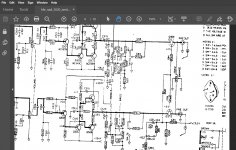
Lets try this in order. Refer to the diagram attached which as far as I know is for a 3020A.
Remove the short and lets have it all back to original.
1/ Measure the DC voltage on the end of D507 that has a stripe. This is the end that goes to the FET gates.
What voltage do you see and also does the sound appear?
2/ Do the same for the other end of D507.
What voltage do you see and also does the sound appear? (polarity is all important for ALL the tests we do here)
3/ You say that:
The R548 has 48V one end 28 at the other
The 28v sounds correct but the 48 does not.
Is the '48' positive or negative in value. If it were negative then it would fit with the fault.
Let us get to that point and analyse what is going on.
Hi Peter - not sure if it helps, but I've just marked up an old photo of the muting area in 3020A with the main components. If you zoom into the photo the labels should be legible. The resistor codes that you need can mostly be read directly on the pcb / in the photo.

If yours looks different to the photo, please try to post a photo of yours.
If yours looks different to the photo, please try to post a photo of yours.
OK Thanks for that. I'll do all that tonight or tomorrow. One thing I forgot to mention. I measured the voltage on the third pin on the mains switch. It showed something like negative 58 volts DC. I'll remeasure that too. Not sure if it helps. On the R548 I don't remember if the 48 V was negative or not.
That's a big help Goldie 
I'll add another quick test having seen that:
4/ The red and white wires to the switch SW-1C. If you measure from ground to each wire what voltages do you see? That's two readings.
5/ Without touching the mains switch at all try unplugging the amp from the wall and then carefully measure between the red and white wires using a low ohms range on your meter. Is the switch reading low resistance?
Thanks Goldie.To me it looks exactly the same but will double check. The picture is very clear. I am not quite sure how to upload pictures on this site but I'll try if I have to.
OK Thanks for that. I'll do all that tonight or tomorrow. One thing I forgot to mention. I measured the voltage on the third pin on the mains switch. It showed something like negative 58 volts DC. I'll remeasure that too. Not sure if it helps. On the R548 I don't remember if the 48 V was negative or not.
Negative 58 sounds OK but it should only be on one of those wires.
If the switch contact is closed then it would apply the high negative voltage onto one side of D507 and that would turn the FET's off and give no audio.
In that scenario you would get sound by connecting your meter to the other end of D507 as your meter would have sufficient resistance to pull the gate of the FET toward ground (and so turn it on).
The negative voltage if present on the other end of D507 actually turns the FET's off but does so in a rather special way relying on leakage current. It works because the FET gates have almost infinite 'resistance' and so they can be pulled negative by the minute leakage current of the diode. Its a neat trick.
Thanks Goldie.To me it looks exactly the same but will double check. The picture is very clear. I am not quite sure how to upload pictures on this site but I'll try if I have to.
We've got that covered as well 😉
How to attach images to your posts.
Later

Yes, thanks, I've studied the attachment upload tutorial but in this case there is no need. Goldie's picture is perfect and it's exactly the same as my amp. These are the measurements, I set the meter on DC:
Red wire 56V negative
White wire 20-21V also negative. Doesn't stay steady
Not quite sure how to measure the resistance, I had the meter on Ohms and with the plug out of the wall it showed something like 120 k ohm when I touched either the red or white wire.
D507 Negative 0.14 and the sound is on
the other end is negative 22V no sound
R548 28V one end and negative 28 the other
Hope this helps. I disconnected the short.
And one more thing to add. I've remeasured the third pin on the switch, right next to the red wire and I still got negative 57 volts DC and the other pin had 0 on it
Yes, that helps and makes sense.
There are not many possibilities here... look at the circuit diagram.
We have R548 (I think it is an 8 and not a 6) and R547 in series and across the approx +29 volt supply.
That generates a voltage of approx +20 volts at the junction of the two. D507 and the 10 meg resistors are way to high in value to alter that result. That is calculated using ohms law, 29v across the two resistors splits into 20v across the high value one and 9 across the other.
So you should be seeing that positive voltage at that point (D507) and you are not.
The fault is going to be around that negative rail generator and depending on weird and obscure failure modes could be any of those three caps, the two diodes and (unlikely now given your readings) the switch.
Diagnosis at this point would involve a quick check with an oscilloscope to see if the negative voltage you read is a true negative or whether it is a spiky AC waveform.
The 'scope would be the correct tool to use at this point but as I assume you don't have one then I think we just have to look at replacing those caps first, the diodes being less of a suspect.
Other obscure reasons would be leakage on the board caused by spillage or similar but I guess that is not likely as you 'know' the amp from new.
Do you have any small caps of those values and voltages?
I'll throw some possibilities into that simulation I did earlier and see what that comes up with 😉
And one more thing to add. I've remeasured the third pin on the switch, right next to the red wire and I still got negative 57 volts DC and the other pin had 0 on it
Any lingering doubts on the switch )is it electrically leaky or is it not) can be 100% proved by quickly disconnect just one lead from it, either at the switch or board end. Board might be better as the switches are easily damaged by excess heat.
I'll throw some possibilities into that simulation I did earlier and see what that comes up with 😉
Quite a few scenarios are possible that could cause this but those 3 caps, the two diodes (not D507) and the switch covers all of them.
C531 leaky will do it. This and C533 have to be favourites.
The switch being leaky will do it. Disconnect a lead to prove.
C533 open circuit gives a really spiky negative rail which would do it.
D505 leaky or short circuit would give a spiky and low negative voltage on D507 as viewed on a scope.
I have a rough simulation, and it all seems consistent with a leaking C531 - if you have any caps with voltage rating 63V or higher, and say 22 - 100uF, you could try just substituting C531. It'll change the start-up muting time (22uF is a second or two in my simulation, and 100uF up to 20 seconds or so), but either should give you working audio - just to 'prove' the fault.
C531 is the most 'stressed' as far as I can see (I'm no expert !), so it's likely to be the first to fail, but the others are not likely to be far behind - but, as Mooly said, identify & fix the problem before changing other things.
C531 is also the failed cap I've found in at least 3 other examples.
That and C533. In some ways I think C533 is maybe the more highly stressed of the two. One sees more voltage, the other passes ripple current.
😀 It is most likely one or the other.
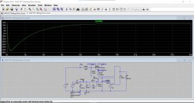
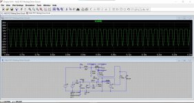
This shows the voltage you should see on D507 over time. These diagrams are how an oscilloscope would show them. D507 settles to a positive value. Once the voltage crosses the approx 0v point the sound unmutes.
First up is all working OK.
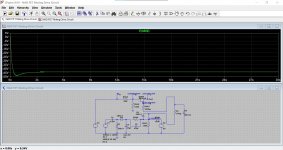
Second is a leaky C531 with 20k leakage. The switch would give identical symptoms if leaky.
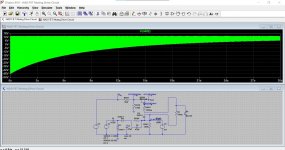
Third is with C533 open. This cap passes a relatively high ripple current and so that makes it likely to go high E.S.R (equivalent series resistance) meaning it loses goodness.
The waveform appears as a solid colour because it is actually an AC value. If we look at a smaller time period (like on a scope) we would see this (fourth image).
😀 It is most likely one or the other.
This shows the voltage you should see on D507 over time. These diagrams are how an oscilloscope would show them. D507 settles to a positive value. Once the voltage crosses the approx 0v point the sound unmutes.
First up is all working OK.
Second is a leaky C531 with 20k leakage. The switch would give identical symptoms if leaky.
Third is with C533 open. This cap passes a relatively high ripple current and so that makes it likely to go high E.S.R (equivalent series resistance) meaning it loses goodness.
The waveform appears as a solid colour because it is actually an AC value. If we look at a smaller time period (like on a scope) we would see this (fourth image).
Attachments
- Home
- Amplifiers
- Solid State
- Nad 3020A developed problems