I got the opamp version to be even simpler 🙂 You have a stable 6v supply for that LED driver and so we can use that as both supply and a reference voltage.
So just one opamp (741 type) and two resistors to set a reference voltage on the inverting input.
It seems to work well and I've tried it for real.
Tomorrow 🙂

So just one opamp (741 type) and two resistors to set a reference voltage on the inverting input.
It seems to work well and I've tried it for real.
Tomorrow 🙂
The NAD 3020 is a classic. Cheply built (so they could sell cheap), the designer very skilled at getting decent sonics out of cheap parts.
We sold many 100s of them (i include the 7020), many getting an additional amplfier and use it just s a preamp (typically PS Audio [the 40w brick], Quad 303, Hafler DH200).
I had one client who came back years later to thank me for selling him Linn LP12/Grace 707/Grado FTE+ [$30 cart at the time], NAD 3020 and speakers (i can’t recall whether he got bookshelf Bostons or LS3/5A). He became a very highish end guy building most of his own gear.
I also had a client go thru (not quite as throroughly as the OP) his 3030, replace every cap with a better one and various other tweaks, became a real sleeper.
dave
Yes, I used just the preamp section for a long time. On the recommendation of an experienced technician in the 3020, I loaded the output with two R of 100 Ohms each and shorted the input with two "special" RCAs for protection of the output stage. I am not very clear at this moment the reason for that recommendation, I have already forgotten it, I think that on the one hand we avoid any noise induced in the input that remains "open", and on the other hand we protect the output TRs with a load impedance very high.The NAD 3020 is a classic. Cheply built (so they could sell cheap), the designer very skilled at getting decent sonics out of cheap parts.
We sold many 100s of them (i include the 7020), many getting an additional amplfier and use it just s a preamp (typically PS Audio [the 40w brick], Quad 303, Hafler DH200).
I had one client who came back years later to thank me for selling him Linn LP12/Grace 707/Grado FTE+ [$30 cart at the time], NAD 3020 and speakers (i can’t recall whether he got bookshelf Bostons or LS3/5A). He became a very highish end guy building most of his own gear.
I also had a client go thru (not quite as throroughly as the OP) his 3030, replace every cap with a better one and various other tweaks, became a real sleeper.
dave
In all those years, the NAD fed all kinds of speakers, fully complying with all of them. And I only had to change the electrolytics and the diode bridge of the PSU ( I am crossing my fingers at the moment, he is in front of me, I currently use it for PC sound ).
Best of luck in that project, and if you allow me an opinion, I would leave the original LED's, all red, the carnival is celebrated here only in a few days of February..... 😉 😊
Of course, perhaps the idea is to know the peaks that the amplifier delivers according to the color, when we are far away and with little ambient light...
I bought my 3020 (the first model) in the 70's, I remember that I had at that time a beautiful Akai AA5810 - built like a tank at that - and of course, when I compared them sonically, I parted with the Akai, quite painfully.
It was like replacing an RR with a VW "Beetle", something classic and solidly built by a bland and boring plastic block, I remember my wife's astonishment when she saw the new amp, I started to explain to her, but she cut me off with a dry "is well, don't explain anything to me, you're the one who knows " .....just when I was going to tell him that the new amplifier's output TRs had complementary output TRs and .... 🤣
I'll follow this thread, best of luck to the OP and I'll surely learn something new.
http://www.gerardslikker.nl/akai-aa5810.htm
do you still need these?OK. The simple FET version is the one that would need 'proving' for real if that is the version you go for.
For the FET version would help to know the voltages you have for real at these four points and to measure them with the switch in each position. It doesn't matter which channel you use, both are the same and we only use one. Although the diagram shows the voltages and we can calculate them... it is a NAD 😉 and you never know if anything is different to the manual.
So with soft clip off.
A=
B=
C=
D=
And with it on.
A=
B=
C=
D=
View attachment 1071465
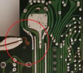

Yes, good point about fillers and glues generally. Retail epoxy products tend to be too viscous or stiff to be absorbed and bond properly with plastics and metals, as they are often assumed to. The way around the problem is to roughen and pre-heat the surfaces to be bonded or filled and follow up with a gentle, low heat blow from a hair dryer or similar after the the gunk is applied. Obviously, you don't apply enough heat for the gunk to become fluid and cure in seconds flat or catch fire, but a little heat over some minutes will accelerate the hardening dramatically as well as aid the 'wetting' of the surfaces to be bonded.👍 Actually super glue is really good on PCB material like that. It soaks in and melts and welds together.......
I have used the conductive silver paint on a few occasions, with good results.....
And its application is much easier, so what would be the problem with them ? 🤔
https://es.aliexpress.com/item/1005...bagn=888888&isSmbAutoCall=false&needSmbHouyi= false&albcp=12617803333&albag=119978710517&trgt=296904913880&crea=es1005001605321053&netw=u&device=c&albpg=296904913880&albpd=es1005001605321053&gclid=CjwKCAjw_b6WBhAQEiwAp4HyIA0OZEAIdyzTm_Vi15uU0tqZClmlWAYOkkI9ovB_ejy5aK0MxurUOhoC_mcQAvD_BwE&gclsrc=aw.ds&aff_fcid=ae40c2ba61674f2c8a89fd1817af62ab-1657828331636-00456-UneMJZVf&aff_fsk=UneMJZVf&aff_platform=aaf&sk=UneMJZVf&aff_trace_key=ae40c2ba61674f2c8a89fd1817af62ab-1657828331636-00456-UneMJZVf&terminal_id=07aff9387ecc485ab4505144edd2adb0&OLP=1082800308_f_group0&o_s_id=1082800308&afSmartRedirect=y
what are you talking about ? 🤨I have used the conductive silver paint on a few occasions, with good results.....
And its application is much easier, so what would be the problem with them ? 🤔
https://es.aliexpress.com/item/1005...bagn=888888&isSmbAutoCall=false&needSmbHouyi= false&albcp=12617803333&albag=119978710517&trgt=296904913880&crea=es1005001605321053&netw=u&device=c&albpg=296904913880&albpd=es1005001605321053&gclid=CjwKCAjw_b6WBhAQEiwAp4HyIA0OZEAIdyzTm_Vi15uU0tqZClmlWAYOkkI9ovB_ejy5aK0MxurUOhoC_mcQAvD_BwE&gclsrc=aw.ds&aff_fcid=ae40c2ba61674f2c8a89fd1817af62ab-1657828331636-00456-UneMJZVf&aff_fsk=UneMJZVf&aff_platform=aaf&sk=UneMJZVf&aff_trace_key=ae40c2ba61674f2c8a89fd1817af62ab-1657828331636-00456-UneMJZVf&terminal_id=07aff9387ecc485ab4505144edd2adb0&OLP=1082800308_f_group0&o_s_id=1082800308&afSmartRedirect=y
what are you talking about ? 🤨
Exactly what I wrote, what is the part you don't understand ?
This type of conductive paint was never mentioned in the discussion.
There it is a question of glue or resin to repair a pcb, not a pcb track, and besides I will not venture to repair a track with this thing.
There it is a question of glue or resin to repair a pcb, not a pcb track, and besides I will not venture to repair a track with this thing.
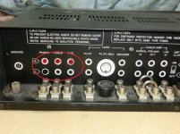
So I was thinking, just thinking at the moment about possibly converting the back panel so that all of the connections are on the rear as shown, including the clip switch and speaker terminals. I may do it on an old one to see what it looks like, but I thought I might get some of you guys opinions. Would it look good or would it spoil the original look and concept of the amp?
Attachments
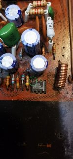
so the op amp position is set for the soft clip LED and pin 4 will connect to ground on C703 and this will anchor it
I just need another op amp now as the one i was going to use ,one of the pins snapped when i was messing around with it
not sure yet if this one is any good, but its good as a template
once it is all finished ill fill all the holes in nicely
I just need another op amp now as the one i was going to use ,one of the pins snapped when i was messing around with it
not sure yet if this one is any good, but its good as a template
once it is all finished ill fill all the holes in nicely
Attachments
It was a separate concern from the OP's work and the PCB crack....This type of conductive paint was never mentioned in the discussion.
There it is a question of glue or resin to repair a pcb, not a pcb track, and besides I will not venture to repair a track with this thing.
But you kind of leave the question open with that paragraph.
Why ? Does it deteriorate over time? and/or is not a good driver? Just give me a reason, a reason that explains why you don't use it, I wouldn't want to dirty the OP's thread, nor open a new thread about "how to repair PCB traces", there must already be many. Just tell me that. Thanks.
im not sure what it is you are asking?It was a separate concern from the OP's work and the PCB crack....
But you kind of leave the question open with that paragraph.
Why ? Does it deteriorate over time? and/or is not a good driver? Just give me a reason, a reason that explains why you don't use it, I wouldn't want to dirty the OP's thread, nor open a new thread about "how to repair PCB traces", there must already be many. Just tell me that. Thanks.
….converting the back panel so that all of the connections are on the rear...
Something i have thot about more than once, More convient, more solid, and you can use better RCA connectors. In the end i just kept my 7020 that already has them on the back.
dave
It doesn't matter, forget it.im not sure what it is you are asking?
What I meant was I didn't know if it was suitable at the time, not if it was any goodIt doesn't matter, forget it.
- Home
- Amplifiers
- Solid State
- NAD 3020 project, strip down and upgrade.