Anyone tried to replace the old AD712? Seems like Burr Brown OPA1612 could be a good candidate.. Anyone knows?
Hej,Anyone tried to replace the old AD712? Seems like Burr Brown OPA1612 could be a good candidate.. Anyone knows?
When I look to the diagram of the circuit I don't see that the IC AD712 is doing much on the signal path. I think is used more as a comparator controlling the relays RL201, when amplifier is overloading or something like that.
I am not sure. Somebody who can bring some more light on this issue?

I’ve got my 216 now and caps are 25x52mm. Hard to find replacements, all today seems to be 30-35mm in diameter. I ordered 4x12000uf /80v Nippon SMH. Only 2000h caps but guess i haven’t anything else to do when they need replacement
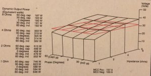
Down below a pic from Swedish Hifi&Musik nr 1-2000 when they tested this amp (and 116 pre) and did some measuring. Very powerful in my eyes in standard config 6x4700uf)
Then i took a pic of my amp and it’s manufactured 1994. Later in -95 the ”Holmgren” or ”Hölmgren” sticker came to stay on it.
Listened to it now for maybe 10hours and quite impressed. Good 3D, relaxed and powerful. Little laid back english ”soft” sound. Treble feels a bit coloured and ”electric”. Bass a bit too swampy. Mid is open and airy. Best part with this amp..
Attachments
I’ve got my 216 now and caps are 25x52mm. Hard to find replacements, all today seems to be 30-35mm in diameter. I ordered 4x12000uf /80v Nippon SMH. Only 2000h caps but guess i haven’t anything else to do when they need replacement ��
Down below a pic from Swedish Hifi&Musik nr 1-2000 when they tested this amp (and 116 pre) and did some measuring. Very powerful in my eyes in standard config 6x4700uf)
Then i took a pic of my amp and it’s manufactured 1994. Later in -95 the ”Holmgren” or ”Hölmgren”���� sticker came to stay on it.
Listened to it now for maybe 10hours and quite impressed. Good 3D, relaxed and powerful. Little laid back english ”soft” sound. Treble feels a bit coloured and ”electric”. Bass a bit too swampy. Mid is open and airy. Best part with this amp..
I think the amp is very good, if you think about the price/Watt.
I think the Toroidal Hölmgren is the source of power that contributes to these fine results.
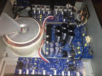
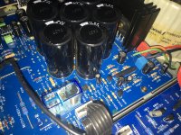
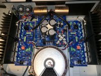
I am rebuilding my faulty 216 with L20 V9 DIY kit using the transformer and some other parts. My primary results are quite good since the transformer is delivering a lot of power. I had to make some changes and add 2 Fans 12 cm in order to matain the temperature low.
The fans will be controlled by 9 V (With a LM7809) in order to keep a very low noise level.
I will publish some pictures in a couple of weeks, but you can see a small part now in the attached picture.
 [/IMG]
Last edited:
Looks good����
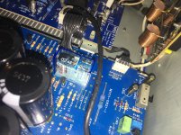
I don’t know if my ears playing with me but i hear a quite big improvement by changing that op amp to OPA1612... feels like level is up atleast 3 db, more hard hitting bass/dynamics better and the whole upper freq. is more smooth and resolved.. now i fon’t skip songs so often for some reason like before.
Yday i changed relay, inputcaps (to Ero MKT 1826 cuz i had them) and 0.01 ceramic to transformer (Wima mkp x2). I think that didn’t do as much.
Overall that little coloured treble and tucked in “english” sound is not so present anymore and i like it. Very open mid now.
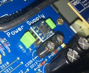
Checked the schematics on 214/216 and saw only 214 have a 10nf cap from centertap to ground but not 216?! My 216 made -94 has but not newer models. What does it do? Better to leave it out? Mine was a ceramic but replaced it for a wima x2 filmcap.
Sorry if this somehow hijacks the thread, but people also mentioned improving the 214. So. I am fixing my 214. Sometimes the sound at one channel disappears during silent passages. Moving the soft clipping switch back and forth fixes this sometimes.
I think the problem is with the relay, and that moving the switch simply causes movement to the board and that helps it. I'm getting a) new relays, b) new main caps (the 4700 uF ones), c) new secondary supply caps (the 160 V 220 uF ones) and maybe new switches for bridge and soft clipping.
I am not into upgrading the main capacitance to an immense amount. I think adding a third pair of 4700 uF is enough. The caps are 22 mm in diameter and 50 mm high. Nichion UVY1J472MRD are a perfect fit.
For the secondary power supply I will have Panasonic EEU-EE2C221S. These are 160 V 220 uF, 18 mm in diameter and 25 mm high (the originals are 35 mm). I heard that Omron G2R-2-DC48 is a perfect replacement for a relay.
But I can't figure out what to do with the switches. The bridging switch is a SK-42F28-G6TS (presumably a C&K part number). The SK means miniature slide switches. The 42 is 4PDT (four pole, double tap), F that the actuator moves 3.0 mm, 28 is just a number. The 6 is the length of the actuator. The G and TS are lost to me. Sometimes there is NS in place of TS, signifying non-shorting. So what is TS? Tolerably or totally shorting?
The soft clip switch is SK-22F28-G9TS. Did someone manage to remove the soft clipping circuit without causing the protection to engage permanently?
I have set the idling currents according to the service manual.
What other parts would you replace at the same time?
Last edited:
You probably don't use the switches much , if ever, so they are not worn out. Cleaning them with Deoxit is preferable to the invasive attempt to replace the switches which might cause other problems.
Amazon.com : Caig Labs. CAIG DeOxit Cleaning Solution Spray, 5% spray 5oz (Limited Edition) : Garden & Outdoor
For relay discussion, see: Replacement output relays for NAD 214/216 AMP
Amazon.com : Caig Labs. CAIG DeOxit Cleaning Solution Spray, 5% spray 5oz (Limited Edition) : Garden & Outdoor
For relay discussion, see: Replacement output relays for NAD 214/216 AMP
Last edited:
Measuring the capacitance of the 220 uF 160 V electrolytics, C210 and C212, while short-circuiting R203, gave me a reading of 418 uF. That is in spec. Wonder if I should or need to replace these at all.
The main caps are rated 2 x 4700 uF = 9400 uF. The meter says they are now at 8200 uF, both positive and negative rail. Seems like the only thing I really need to keep on going is to replace the relay.
But if I decide to ensure that everything is properly soldered, do I just need to reheat every single joint and then quickly allow to cool? Or should I remove the old and reapply new? Or apply a slight amount of flux, then reheat and let cool? What would you do?
I recommend a minimally invasive approach. Replace the relay, clean the switches, visually inspect the solder joints and only reheat those that look bad. Add a pair of 4700uF caps if there is room for an extra pair. Measuring caps in circuit may not yield accurate results so you shouldn't make judgements about the capacitors based on those measurements. After doing the steps I listed, test the amplifier and see if it has returned to full performance. If it has, return it to service and enjoy the music.
Hello
One 214 has now a new relay and six new capacitors. RCA connector and the slide switches have their pins reheated with flux and some solder added to a few pins that looked like needing it. Plays fine.
Decided to tune the idle current before screwing the cover on. My problem is, between the jumpers mentioned in the service manual, there is about 30 mV. Turning the pot changes this slightly but far from enough. It's the same after letting it stay on for ten or fifteen minutes.
Am I making some regular mistake here, or do the pots need replacing? This is with two different multimeters and both channels.
I also measured the former four capacitors after taking them out. They were around 4150 uF all of them, which is below -10 % but clearly within -15 %.
Ouch! J301 is different from TP301. That was the problem.
Last edited:
Umm. No. I just confused the measurement points. The pots are quite stable and have been since last adjustment a few years ago.
Funny thing is that you can make the voltage wander around more than 10 % just by blowing onto the heatsink. So I decided to let it settle on maybe 19.7 mV and look at the multimeter from afar.
Also, the problem with the slide switches that the soft clipping light was sometimes on even if the switch was at the off position is now gone. And both channels have now operated continuously, most probably due to the new relay.
This is exactly how thermal compensation works, otherwise the bias current would rise as the output stage warmed up and continue to rise until the power semis burned up. The magic smoke would escape and of course, nothing would work unless a fuse saved the day 😱.....Funny thing is that you can make the voltage wander around more than 10 % just by blowing onto the heatsink....
I noticed this amp sounds better eith bias turned up to 33ma... i accidently did it and got used to it but now at 18ma it sounds little mediocre. In comparison so wonder anyone knows hoe much i can turn up bias? At 33ma the amp got quite hot...
Disconnecting the soft-clip circuit is probably a good idea, its really just lowering the distortion-free headroom of the amp - my feeling is that if an amp is clipping you either need to turn the volume down or get a more powerful amp, not listen to intermodulation products generated at the peaks of strong bass notes.
A simple diode clipping circuit is pretty naive - you are really just changing a harsh loud clicking to a slightly less harsh loud clicking, as well as introducing distortion to all signals at near full volume.
A simple diode clipping circuit is pretty naive - you are really just changing a harsh loud clicking to a slightly less harsh loud clicking, as well as introducing distortion to all signals at near full volume.
I would like to do that but not sure exactly where to disconnect it. Somebody tried here i think but then the amp didnt work..
- Home
- Amplifiers
- Solid State
- NAD 216 THX - Make it sound better?