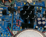
IC202 controls the muting and protection. Let's take a look at the voltages around that chip. It is located in the lower left (circled in red in the attached picture). Pin 1 is on the bottom , pin 9 at the top.
If your meter is not autoranging, then set it to the 20 VDC range. With power on, and being sure you have a good ground measure the voltage at each of the pins. I would expect:
Pin 1 = Less than 1 volt
Pin 2 = Very near 0 volts
Pin 3 = Very near 0 volts
Pin 4 = 0 volts (this is ground for the chip)
Pin 5 = -0.7 volts
Pin 6 = 0, this will be much higher (60 volts) if the protection relay is not pulled in. Set the meter to the 200 VDC range to measure it.
Pin 7 = 0 volts
Pin 8 = 1.3 volts
Pin 9 = 3 volts
Oh, and if you haven't already, you will need to plug the amplifier boards back in for these measurements.
For reference, an old post on the TA7317 protection chip:
TA7317 protect circuit in NAD 319
Attachments
Last edited:
a little sidenote, i still have or atleast i think i have a dead diod D214 (in the protection unit) cant get any reading out of it more then a long beeeep on my multimeter.
and lastnight i placed a random electrical parts since i dont have much at home.
and lastnight i placed a random electrical parts since i dont have much at home.
In addition to the above measurements, with power on measure the voltage at D214 unbanded end. If unsure of which end is unbanded, measure both ends.a little sidenote, i still have or atleast i think i have a dead diod D214 (in the protection unit) cant get any reading out of it more then a long beeeep on my multimeter.
???and lastnight i placed a random electrical parts since i dont have much at home.
D214 banded side = 0v , unbanded side = 0.200v
what i meant was that i placed an order of resistors, diods and caps in case of.
and one more thing that ive noticed when i turn the amp on now is that its going directly in protection mode and the bridge mode lamp lights up for 2-3sec in spite of having it turned on
what i meant was that i placed an order of resistors, diods and caps in case of.
and one more thing that ive noticed when i turn the amp on now is that its going directly in protection mode and the bridge mode lamp lights up for 2-3sec in spite of having it turned on
Last edited:
OK, let's check the voltage on both leads of R244.
R244 = -67v and .200 on the other side
Results from IC202
Pin 1 = -0.685v
Pin 2 = 0.782v
Pin 3 = 0.783v
Pin 4 = 0v
Pin 5 = -0.732v
Pin 6 = 55.5v
Pin 7 = 0v
Pin 8 = 0.581v
Pin 9 = 3.1v
Pin 1 = -0.685v
Pin 2 = 0.782v
Pin 3 = 0.783v
Pin 4 = 0v
Pin 5 = -0.732v
Pin 6 = 55.5v
Pin 7 = 0v
Pin 8 = 0.581v
Pin 9 = 3.1v
I think you are going to need to replace that Zener diode. (I think you were suspicious of that part a while back - good catch!)
It is a 15 volt, 0.5 watt Zener diode. Don't know what you have available locally, but here in the US I would order a 1N5245B. Also see BZX79C15 (ON Semi) and BZX55C15 (Vishay) among others.
It might also be a bad Op-amp, IC201, an AD712. If you are ordering parts, you might want to get one of those too.
Last edited:
Results from IC202
Pin 2 = 0.782v
Pin 3 = 0.783v
These would indicate both channels have excessive offset.
Pin 8 = 0.581v
A bit low, but it might return to normal once those output offsets are fixed.
I think you are going to need to replace that Zener diode. (I think you were suspicious of that part a while back - good catch!)
It is a 15 volt, 0.5 watt Zener diode. Don't know what you have available locally, but here in the US I would order a 1N5245B. Also see BZX79C15 (ON Semi) and BZX55C15 (Vishay) among others.
It might also be a bad Op-amp, IC201, an AD712. If you are ordering parts, you might want to get one of those too.
that diod i can get tomorrow but the IC unit ill have to order...
wasnt it IC202 ??
Try the diode first. And you might want to check for +15 volts on the other IC power pin too.
IC202 is the protection IC. At this point, I don't think that one is bad.
IC201 is part of the DC servo loop that holds the amplifier output channels to 0 volts with no signal in. If that is not working, either because it is not getting it's supply voltage (bad D214) or the IC itself is bad, the output offset will not be corrected.
So we are first looking at D214, and if that does not correct the issue then you may need to replace IC201.
@ Ylli just a note on my NAD 216 the voltage on IC201 wasnt correct on one side until i replaced a open resistor on my left amp board. it was R317 a 160k metal film 1%

Nad 216
Guys my lovely 216 stopped abruptly with no audio o/p,and i found your post here.
I was very impressed with all of your knowledge Ylli Sqeek jesseewing and approach here in particular (Sqeek)the marked voltages on the diagram.
Had mine fixed in 30 mins .
No vol -67 because fusible R202 was open.
I am new here and would like to thank you all for this and hope i can bring some useful fixes to this forum like you guys can do
Joe
@ niceguy9 your welcome and good for you nice job happy to hear that you got it sorted will minimal trouble i agree this is a great forum.
Chaps, I apologise for dredging this thread up, but I also have a red light on my NAD 216.
I've done most of these voltage measurements also, (although not the transistor ones as I haven't got in there yet)
I have 60V and -60 (and the 67,-67) where they should be.
I do have a nasty looking capacitor though ( C214)
Is this a likely culprit? Or should I be doing more digging?
I've done most of these voltage measurements also, (although not the transistor ones as I haven't got in there yet)
I have 60V and -60 (and the 67,-67) where they should be.
I do have a nasty looking capacitor though ( C214)
Is this a likely culprit? Or should I be doing more digging?
Attachments
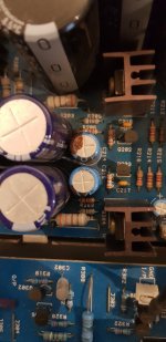
Your photograph shows brown glue used during manufacture it is not the capacitor leaking.
Can you check the plus and minus 55 Volt rails are present?
Plus 55 Volts should be present on one end of R212 and Minus 55 Volts should be present on one end of R217
If the voltages are present can you disconnect the left and right Amplifier modules, then power on the Amplifier and check if the LED turns green and the speaker protection relay turn on after approximately 5 seconds.
If the LED goes green and the relay operates switch off the Amplifier and connect the right channel module and repeat the test.
If the LED goes red, again turn off the Amplifier disconnect the right channel module and then connect the left channel then repeat.
You should be able to quickly verify if you have an issue with either module causing the Amplifier to switch to protection.
- Home
- Amplifiers
- Solid State
- NAD 216 red protection problem