There is no trick to it, just physics.
Twice as big an OT giving twice as much power capability as a result.
Have some coffee, clear your mind, then consider:
If one OT primary can handle X amount of current and Y amount of voltage, then two primaries in series (effectively) handle the same X amount of current but now twice Y amount of voltage. So twice the power in. This is the primary side.
Secondary side:
The 16 Ohm secondaries are paralleled to form an 8 Ohm result. The 16 Ohm taps each handle 1.414x the amount of voltage of an 8 Ohm tap. And they handle .707x the current of the 8 Ohm taps. When paralleled, the result is 1.414x the voltage (of original 8 Ohm out for one OT) and 1.414x the current (1.414 = .707 + .707). Watts rating is VxI so 1.414 x 1.414 = 2X the power out compared to the single OT. 2X in, 2X out.
2nd law of thermodynamics is still intact.... Can relax now.
Last edited:
as i understood it, the whole point of this Crowhurst design is to be able to use cheap output transformers and still get a very good sq.....i guess the complexity of it was the thing that put off many diy'ers......
because with tubes, even minimalist and simplistic designs can really deliver the goods...
i do not know how many fans are out there of the MC275 which was the offshoot of this design, would anyone know how many MC275's were made and sold?
i am never a big fan of complicated circuits with so many tubes in the signal path, and so many coupling caps, simply not my cup of tea....
There is no trick to it, just physics.
Twice as big an OT giving twice as much power capability as a result.
Have some coffee, clear your mind, then consider:
If one OT can handle X amount of current and Y amount of voltage, then two primaries in series (effectively) handle the same X amount of current but now twice Y amount of voltage. So twice the power in. This is the primary side.
Secondary side:
The 16 Ohm secondaries are paralleled to form an 8 Ohm result. The 16 Ohm taps each handle 1.414x the amount of voltage of an 8 Ohm tap. And they handle .707x the current of the 8 Ohm taps. When paralleled, the result is 1.414x the voltage (of original 8 Ohm out for one OT) and 1.414x the current (1.414 = .707 + .707). Watts rating is VxI so 1.414 x 1.414 = 2X the power out compared to the single OT. 2X in, 2X out.
2nd law of thermodynamics is still intact.... Can relax now.
i agree....
I think you're on to it there. A 211 SET is a piece of cake now except for the KV B+ supply.
Only issue I have with this whole impedance doubler scheme is the HV B+ safety issue. This all started when the 211 OT thread ran up against a big $$ 1000 $$ wall, for a 16K Ohm OT. Not the kind of tubes I would play with, but others have different ideas, I know.
I'm still more interested in getting a "shunt Schaded" beamer to emulate these "perfect triode" types well. I know you have worked on the same with the KT88 and 300B in the past too. Also, I like the outright tube emulation schemes using a small model triode controlling a Sweep output. Potentially considerably safer (without a plate cap anyway).
Just look at a 211 or 845 amp the wrong way and static electricity starts crawling on your skin, ready to flash over. Probably part of the excitement I guess. They should have a Tesla coil towering ominously above the chassis.
The McIntosh (published 1949) predated the Crowhurst. I'm not sure about the Circlotron. But these are all deeply related. All can also be arranged for 50% "ultralinear" a la jhstewart, a big advantage with sweep valves' G2 ratings.
For the 50-watter class, not a lot of extra effort is required to use equal B+ and B- supplies, keeping them each to less than 625 VDC. Still a lot, but there it is. Full wave bridge rectifiers from a center-tapped secondary do this naturally.
All good fortune,
Chris
For the 50-watter class, not a lot of extra effort is required to use equal B+ and B- supplies, keeping them each to less than 625 VDC. Still a lot, but there it is. Full wave bridge rectifiers from a center-tapped secondary do this naturally.
All good fortune,
Chris
What I understood cathode turns with SE is normally 10% (at most) of anode turns for an output stage.
That is for "reasonable grid drive". The Crowhurst and the Mac use *monster* drivers bootstrapped from the output.
You can't just double the xformer or tube rating with a circuit trick, that is nonsense....
I think the text is unclear. He proposes two 30W transformers to handle one 60W output, which you will agree does not violate common sense. It still needs the tube capable of 60W output. However old transmitter tubes are mildly easier to find than monster output transformers, especially for SE (a single or stereo-pair of tubes is easy, a single SE OT over 30W is harder/costlier).
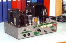
For my take on the Circlotron/Electrovoice cct I did use two OPTs as one of three alternate OPT arrangements. I reasoned since two Rs or two Cs could be paralleled for lower impedance & higher power handling, why not parallel two OPTs. So I used a pair of Hammond 125Es on the 6L6GC vers of the amp. That worked OK, no laws of gravity where broken or otherwise.🙂
That one done around the same time as the two Norman Crowhurst Twin Coupled projects.
That one done around the same time as the two Norman Crowhurst Twin Coupled projects.
I date from the year after the McIntosh paper (I remember vividly reading it in my crib) and IIRC, so does PRR. That makes you a genuine geezer. Have they taken away your car keys yet? Don't let 'em!
Much thanks, as always,
Chris
Much thanks, as always,
Chris
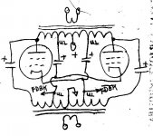
This should help those with trouble comparing the competing OPT hookups to a double wound primary OPT. My very olde hand drawn thing before I got Electronics Workbench.🙂
Thanks, there's both AC and DC to consider of course 😉 Can't recall to have ever seen a gapped PP-OT though but they'll surely exist.
Is that for power only or is there an advantage distortionwise?That is for "reasonable grid drive". The Crowhurst and the Mac use *monster* drivers bootstrapped from the output.
😀)Have they taken away your car keys yet? Don't let 'em!
Last edited:
> Have they taken away your car keys yet?
The eye-glasses guy said I was not legal to drive, and he could not help me. But he knew a guy with a knife and now I see better than new. Other guys with knives have taken-away other bits. However the Mac paper is actually a bit before my time.
The eye-glasses guy said I was not legal to drive, and he could not help me. But he knew a guy with a knife and now I see better than new. Other guys with knives have taken-away other bits. However the Mac paper is actually a bit before my time.
Some Notes on Project Construction
If we throw enough money at a project anything is possible. But the Law of Diminishing Returns soon becomes a problem. So I’ve tried to keep the cost down, I couldn’t afford all those fancy, boutique part’s. And otherwise hard to find component’s.
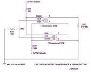
For the amateur builder of the Circlotron, the OPT is a problem. The OPT impedance match is one forth of what the normal PP connexion is. For example, a common mode of operation for 6L6GC’s is 6600Z, plate to plate. That means the Circlotron needs an OPT of 1650Z. There are OPTs of that impedance match but they are very large & expensive. An easy way out for a ‘one of’ build is a pair of low cost ordinary OPTs. I already had a Hammond 125E in my stash so I bought another for the project. But for experimental use I also bought from Hammond a made to order OPT (H300767). That way, considerable measurement data could be had.
Referring to the hookup for the pair of H125Es, each OPT sees a load of four ohms. So four ohms connected across taps 1-5 reflects 2800Z to the primary. The pair of H125Es present a load of 1400 ohms when connected in parallel. I’ve also reversed the respective primary & secondary lead connexions in order to cancel winding capacity to core imbalance. Refer to the note covering that issue.
For PP pentode amps I usually set the load match lower than that shewn in the tube manuals. For a working amp the load is complex, a loudspeaker. For much of program material, the loudspeaker is impedance is above the published value. And the published value is for maximum power into a resistive load. Not the same thing.
It was unlikely I’d find on the market a single power transformer with all the windings required for this kind of project. An identical pair of Hammond PTs was the way forward. That arrangement allows all the tubes to be connected so that none are stressed by H-K insulation problems. Refer to the schematic.
Notice many 10R & other like resisters in seemingly odd places in my schematics. That is a holdover from my time in the R&D lab, a convenient way of measuring conditions in a working cct. Very handy & saves considerable time. And might detect a problem before smoke appears.
I’m a strong believer in lots of measurement data, what works & what doesn’t. Some results are in the attachments.🙂
If we throw enough money at a project anything is possible. But the Law of Diminishing Returns soon becomes a problem. So I’ve tried to keep the cost down, I couldn’t afford all those fancy, boutique part’s. And otherwise hard to find component’s.
For the amateur builder of the Circlotron, the OPT is a problem. The OPT impedance match is one forth of what the normal PP connexion is. For example, a common mode of operation for 6L6GC’s is 6600Z, plate to plate. That means the Circlotron needs an OPT of 1650Z. There are OPTs of that impedance match but they are very large & expensive. An easy way out for a ‘one of’ build is a pair of low cost ordinary OPTs. I already had a Hammond 125E in my stash so I bought another for the project. But for experimental use I also bought from Hammond a made to order OPT (H300767). That way, considerable measurement data could be had.
Referring to the hookup for the pair of H125Es, each OPT sees a load of four ohms. So four ohms connected across taps 1-5 reflects 2800Z to the primary. The pair of H125Es present a load of 1400 ohms when connected in parallel. I’ve also reversed the respective primary & secondary lead connexions in order to cancel winding capacity to core imbalance. Refer to the note covering that issue.
For PP pentode amps I usually set the load match lower than that shewn in the tube manuals. For a working amp the load is complex, a loudspeaker. For much of program material, the loudspeaker is impedance is above the published value. And the published value is for maximum power into a resistive load. Not the same thing.
It was unlikely I’d find on the market a single power transformer with all the windings required for this kind of project. An identical pair of Hammond PTs was the way forward. That arrangement allows all the tubes to be connected so that none are stressed by H-K insulation problems. Refer to the schematic.
Notice many 10R & other like resisters in seemingly odd places in my schematics. That is a holdover from my time in the R&D lab, a convenient way of measuring conditions in a working cct. Very handy & saves considerable time. And might detect a problem before smoke appears.
I’m a strong believer in lots of measurement data, what works & what doesn’t. Some results are in the attachments.🙂
Attachments

OK Chris, for sure I'm a Geezer at 87. Still driving but gave u the bike two years ago. But I meant I did the Circlotron project around the same time as I'd done the Twin Coupled Amps, about 20 yrs ago.I date from the year after the McIntosh paper (I remember vividly reading it in my crib) and IIRC, so does PRR. That makes you a genuine geezer. Have they taken away your car keys yet? Don't let 'em!
Much thanks, as always,
Chris
In 1948 my recollection was an 815 hookup up for whatever, IT driven by a triode connected 6F6, just like in the olde toob manuals. The PT was for the 25 Hz power system running in Southern Ontario at the time. The massive changover to 60 Hz came spread over the next couple of years.
That PT has been working in my regulated PS beginning around 1960. Makes it kinda heavy tho.🙂
Attachments
That is for "reasonable grid drive". The Crowhurst and the Mac use *monster* drivers bootstrapped from the output.
Is that for power only or is there an advantage distortionwise?
Increased % CFB reduces distortion in proportion, but requires a supercharged driver on approaching 50% CFB. 50% CFB for a 211 or 845 is going to take a power tube for the driver. KV B+
------------
For the amateur builder of the Circlotron, the OPT is a problem. The OPT impedance match is one forth of what the normal PP connexion is.
I recently bought a couple of Edcor 1600 Ohm 25 Watt CXPP25-1.6K OTs with 16 Ohm secondary, so it's on their list now.
EDCOR - CXPP25-1.6K
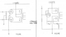
Another solution is to reconfigure the Twin Coupled as the Elliptical Twin (pic below) Then the primary Z stays the same as the xfmr rating (with 16 Ohm secondaries paralleled to form 8 Ohm).
An industrial split bobbin xfmr 230/115 - 230/115 can make a nice cheap floating B+ supply xfmr for Circlotron. (175 Watt model in 2nd Pic)
I measure only 80 pF between the split bobbin windings from side to side in a Stancor TGC175-230 xfmr (175 Watt). And a smaller (43 Watt) Stancor TGC43-230 measures only 53 pF from side to side (good for a floating scrn V supply)
Attachments
Last edited:
I'm still more interested in getting a "shunt Schaded" beamer to emulate these "perfect triode" types well. I know you have worked on the same with the KT88 and 300B in the past too. Also, I like the outright tube emulation schemes using a small model triode controlling a Sweep output. Potentially considerably safer (without a plate cap anyway).
Just look at a 211 or 845 amp the wrong way and static electricity starts crawling on your skin, ready to flash over. Probably part of the excitement I guess. They should have a Tesla coil towering ominously above the chassis.
Yeah, I won't be building a kV B+ amp myself for the same reasons.
I want to build at least one SE amp and I think my next experiments will be with a 40W beam tube (probably KT88, but there is no reason you couldn't adjust screen voltage and use any other beam tube/pentode) as output and current-source drive with shunt feedback. So far, I've never been happy with the linearity of any pentode working into a near vertical load line, even with cathode degeneration, so I'll probably resort to adding an op-amp with a tube in the feedback loop to linearize the V-to-I conversion. Blasphemy to many, but it will be a near 100% voltage feedback amp, which should give really good DF and performance. My push-pull shunt feedback amp was 30% and my Unity-Coupled is of course 50%.
I previously experimented with my (Edcor 5k) SE transformers driving them with a Mosfet follower output device driven from the EL34 driver I linked above. I got over 18W and a measured 0.6 Ohm Zout with no feedback around the transformer, but the mosfet follower wanted to oscillate if you looked at it funny and definitely needed some special taming to be a final version. Probably needed similar measures to solid-state output stages. But I didn't like that approach as the EL34 driver needed 1000V+. Current-source drive into a shunt-feedback network seems to be the elegant approach. Few supplies and a simple/straightforward circuit. Should perform really well too.
I'm curious how close I'll come in practice to the measured Zout of the mosfet SE amp. I will of course have much less gm to work with in the tube but I think copper losses in the transformer will still dominate. Should still be less than an Ohm Zout, which will still be slightly better than my open-loop Unity-Coupled amp.
Is there any advantage to this compared to 60Hz?the 25 Hz power system
That PT has been working in my regulated PS beginning around 1960. Makes it kinda heavy tho.🙂
That power transformer looks to be deeply committed to its task. Yikes.
All good fortune,
Chris
Does anyone have any thoughts about heater - cathode voltage ratings? I notice that damper diodes, who operate "upside down", anode to ground, cathode to very very large positive spikes, are rated for some nominal voltage with heaters positive of cathode but huge voltage with heaters negative of cathode.
Is this actually the case for all valves?
Much thanks for any thoughts,
Chris
Is this actually the case for all valves?
Much thanks for any thoughts,
Chris
- Home
- Amplifiers
- Tubes / Valves
- N. Crowhurst Twin Coupled works for SE too!