... for the 25 Hz power system running in Southern Ontario at the time. The massive changover to 60 Hz came spread over the next couple of years.
Is there any advantage to this compared to 60Hz?
Around 1880 when LARGE power systems were built, ordinary transformer iron had large eddy losses. Less if worked at low frequency. Also most motors were LARGE, powering whole factories, not single machines; again a lower frequency is preferred.
The killer disadvantage of 25Hz is that lamps FLICKER, bad.
Improved transformer iron and the shift to per-machine motors made 50/60Hz the more practical frequency. But the installed investment in 25Hz power was large, especially around Niagara Falls. It was in use into the 1950s, IIRC, which echos JH's explanation.
Actually, Niagara Falls did not decide DC or AC until the turbines were bought. And they are big and slow, so 25Hz was good fit for this and other reasons. Utility frequency - Wikipedia And 25Hz was still in use (if not in JH's house) until 2006. 25-Hz at Niagara Falls
The former Penn Central tracks distributed 25Hz power along their lines, though I believe converted to DC to run the trains, this system has deep history. Amtrak's 25 Hz traction power system - Wikipedia
Last edited:
Does anyone have any thoughts about heater - cathode voltage ratings? I notice that damper diodes, who operate "upside down", anode to ground, cathode to very very large positive spikes, are rated for some nominal voltage with heaters positive of cathode but huge voltage with heaters negative of cathode.
In my Unity-Coupled amp, I bought four small individual heater transformers and referenced each to the cathode of each KT88 output tube in order to be nice to the heater-cathode insulation.
So far, I've never been happy with the linearity of any pentode working into a near vertical load line, even with cathode degeneration, so I'll probably resort to adding an op-amp with a tube in the feedback loop to linearize the V-to-I conversion.
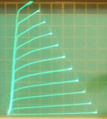
Could use Crazy/Twin drive for a linear V to I driver, but then you are still stuck with driving a grid 2 input for that. Not a whole lot of improvement I guess. (pic 1, 12HL7 going Crazy)
A differential tailed driver (even though for SE) could help linearize the pentode V to I driver.
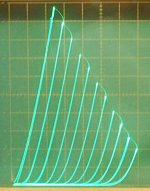
And since some 12HL7 (selected) have a remarkable g2/g1 triode in them (pic 2) you could just move the "shunt Schade" N Fdbk back to one 12HL7 grid 2. Then you don't have any low Z drive problem or V to I linearity problem. Probably make the output stage sound like a 211.
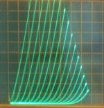
And then... Using Alibaba and the 40 6197 tubes in parallel triode mode (pic 3) (actually more like 16x for a 25 Watt SE, 16 Candles?) one would get curves like a 300B without the shunt Schade" activated, and like the 211 with it activated.
I'm building up a couple of fiberglass boards with 16x 9 pin sockets on them, like pins bussed together, (individual grid 1 stoppers on pin 2, and grid 2 stoppers on pin 8). Can then run 6197, 12HL7, 6HB6, 12BY7, 29GK6 on them.
----
PRR = Pensylvania Rail Road?
Intersting read on Wikipedia about the 25 Hz power.
Attachments
Last edited:
smoking-amp,
Interesting idea you have: long tailed pair to run an SE output stage.
Use one output to drive the output tube.
The 2nd harmonic is reduced in the inverter.
One disadvantage is the gain is 1/2 of using a single stage, versus the long tailed pair.
Also, for the same bias voltage, the maximum swing is also 1/2 of a single stage.
A differential tailed driver (even though for SE) could help linearize the pentode V to I driver.
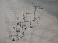
I had thought of using a differential stage with a current mirror load as a V to I converter, like the input stage of a solid-state amp. I think that is one of the better solutions, but I think I may have come up with something better today as I was thinking about this.
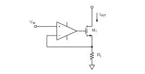
I was considering just using an op amp like the attached image with a tube substituted for the fet but then I decided to try to make a CCS-loaded pentode substitute for the op-amp and see if I could satisfy the DC conditions. I think I found a way to make it work but had to use a p-channel fet. Let me know if you see anything I missed. I think it would be an extremely linear V-to-I converter. I almost thought I was sunk but then came up with the idea of driving the screen of the second tube from the mu output of the CCS, probably best to make that a solid-state CCS for lowest distortion but you could make it from a tube if you just like doing things the hard way...
Attachments
Wouldn't the screen drive generate more distortion?
Have you tried to simulate that in LTSpice?
The mufollower dc coupled to a crazy drive is a great idea and the local loops are very interesting. That fet could benefit if it was a p channel
Have you tried to simulate that in LTSpice?
The mufollower dc coupled to a crazy drive is a great idea and the local loops are very interesting. That fet could benefit if it was a p channel
Aw man, the screen current from the screen drive on the second pentode is going to mess up the current in the current reference resistor. That won't work.
I'll probably have to replace the second pentode with a silicon device.
I'll probably have to replace the second pentode with a silicon device.
Wouldn't the screen drive generate more distortion?
Have you tried to simulate that in LTSpice?
The mufollower dc coupled to a crazy drive is a great idea and the local loops are very interesting. That fet could benefit if it was a p channel
The high gain/feedback would linearize but I forgot that the screen current would go out the cathode and add to the current that I really want to sense for the feedback to work properly.
I haven't tried to simulate anything. This is just a half-baked idea from a couple of hours ago. I don't even have LTSpice installed.
If anything, I think I could replace the screen-drive pentode with an n-channel mosfet with lots of source degeneration so that I could get the dc levels right?
jhstewart9, reading that article is what got me thinking about it and wondering how to do it with more tubes. Honestly, though, I would probably do the op-amp and single transistor if I were to build this. It is so simple and I don't really have a problem with op amps.
Having a tube replace the current-drive transistor creates some challenges since that tube has to operate well in a lower voltage region when the output tube pulls toward saturation. If you have a good output tube, that will pull the plate to a low voltage and that's one of the areas where a transistor has a big advantage over a tube. I think you could pick a pentode that could pull it off, but the transistor is going to be much more comfortable in that region of operation.
Replacing the op amp with a pentode also seems like it could work but it creates other problems due to DC idle condition requirements that don't exist in the op amp. Unfortunately, I think it makes it so that the current-drive device needs a positive turn-on and can't draw current, or maybe it could be solved with a more complex way of biasing that device. It's getting pretty complex to replace a very simple solid-state equivalent.
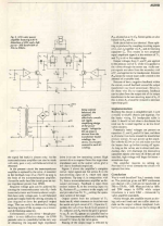
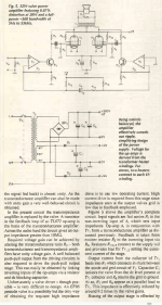
Rest of the Article
A good explanation on these pages. Looks like a way around the driver problem while using triodes or pentodes. There are other ways but this one is very simple & clean.🙂
A good explanation on these pages. Looks like a way around the driver problem while using triodes or pentodes. There are other ways but this one is very simple & clean.🙂
Attachments
-
Transimpedance & Transconductance in Experimental Amplifier p5.pdf531.2 KB · Views: 107
-
Transimpedance & Transconductance in Experimental Amplifier p3.pdf697.1 KB · Views: 83
-
Transimpedance & Transconductance in Experimental Amplifier p2.pdf731.9 KB · Views: 90
-
Transimpedance & Transconductance in Experimental Amplifier p1.pdf653.4 KB · Views: 197

- Home
- Amplifiers
- Tubes / Valves
- N. Crowhurst Twin Coupled works for SE too!