I just noticed that the Norman Crowhurst Twin Coupled design works for SE use too!
Doesn't seem to have been noticed before, almost shocking really. So simple, yet quite useful too.
Since 10K Ohm and above SE (or P-P) OTs are hard to get good results with typically, this provides a means of using lower primary Z, off the shelf OTs to get there. (getting 2X the primary Z) No more custom OTs required. The Watt ratings of the two SE OTs add up too. You need 16 Ohm secondaries, to parallel together, to get an 8 Ohm secondary for the load.
To get a 16K Ohm SE OT say, you would just use two 8K Ohm SE OTs, one for the tube cathode circuit and one for the tube plate circuit.
If you don't want the 50% CFB inherent in the N. Crowhurst Twin, you use the cathode circuit to provide a cap coupled bootstrap boost to the driver stage plate load resistor. A HV pentode or Beamer would be best for driver duty, but not essential. A HV triode driver would leave some CFB effect in place and lower the output impedance too (for improved damping factor and bass).
The little 6GF5 TV Sweep tube (9 Watt) is rated up to 770 V B+, but many others will work too for a driver. (6GF5 is on the $1 list at ESRC)
6S4/A triode is rated 550V B+, and 6SN7 triode is rated 450 V.
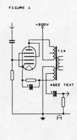
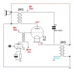
Schematic below of the usual Push-Pull Norman CrowHurst Twin Coupled design for some reference. SE is similar, but just half of the P-P circuit.
I'll have to get another SE OT to try this out now.
Just thought y'all would want to be in on the BIG SECRET! No need to order custom Hi-Z SE OTs anymore.
With a Hammond 30 Watt SE OT (for example) you can make a 60 Watt SE OT now for those really big projects. Their 75 Watt SE can do 150 Watt SE now!
Don
Doesn't seem to have been noticed before, almost shocking really. So simple, yet quite useful too.
Since 10K Ohm and above SE (or P-P) OTs are hard to get good results with typically, this provides a means of using lower primary Z, off the shelf OTs to get there. (getting 2X the primary Z) No more custom OTs required. The Watt ratings of the two SE OTs add up too. You need 16 Ohm secondaries, to parallel together, to get an 8 Ohm secondary for the load.
To get a 16K Ohm SE OT say, you would just use two 8K Ohm SE OTs, one for the tube cathode circuit and one for the tube plate circuit.
If you don't want the 50% CFB inherent in the N. Crowhurst Twin, you use the cathode circuit to provide a cap coupled bootstrap boost to the driver stage plate load resistor. A HV pentode or Beamer would be best for driver duty, but not essential. A HV triode driver would leave some CFB effect in place and lower the output impedance too (for improved damping factor and bass).
The little 6GF5 TV Sweep tube (9 Watt) is rated up to 770 V B+, but many others will work too for a driver. (6GF5 is on the $1 list at ESRC)
6S4/A triode is rated 550V B+, and 6SN7 triode is rated 450 V.
Schematic below of the usual Push-Pull Norman CrowHurst Twin Coupled design for some reference. SE is similar, but just half of the P-P circuit.
I'll have to get another SE OT to try this out now.
Just thought y'all would want to be in on the BIG SECRET! No need to order custom Hi-Z SE OTs anymore.
With a Hammond 30 Watt SE OT (for example) you can make a 60 Watt SE OT now for those really big projects. Their 75 Watt SE can do 150 Watt SE now!
Don
Attachments

Last edited:
There is a small fly in the soup for directly heated valves like the 50-watters, etc. Care must be taken to isolate the filament supplies from signal ground. I'd guess that medical grade isolation transformers upstream from the regular filament transformers should be good enough. Or maybe just "dual-bobbin" construction in the filament transformers. Just needs to be a big impedance relative to the signal impedance at the filaments.
Yet another good reason to like sweep valves - they have cathode sleeves.
All good fortune,
Chris
Yet another good reason to like sweep valves - they have cathode sleeves.
All good fortune,
Chris
I noticed in one of the three articles Crowhurst did on his twin-coupled amp he used EL84s. The H-K rating was exceeded, so I mentioned that in one of the articles I did on the twin coupled. An interesting amp to cover, for myself a great project.
The load impedance is 1/4 of what it would be if in a regular PP amp, so the voltage excursions are much less. So some tubes are OK sofar as H-K insulation might be a problem.
My recollection is all the Hammonds like I used are HiPotted for >1.5KV, should be OK in this cct.🙂
The load impedance is 1/4 of what it would be if in a regular PP amp, so the voltage excursions are much less. So some tubes are OK sofar as H-K insulation might be a problem.
My recollection is all the Hammonds like I used are HiPotted for >1.5KV, should be OK in this cct.🙂
Attachments
With a Hammond 30 Watt SE OT (for example) you can make a 60 Watt SE OT now for those really big projects. Their 75 Watt SE can do 150 Watt SE now!
Don
Interesting design choices but I am not convinced that with an extra xformer now suddenly your amps produce double the power*. Where is that power coming from? You can't create it from thin air. It has to come from the output tube.
Jan
If it was that simple, the worlds' energy problems would be over ;-)
It just doubles the power rating of the SE OT effectively.
It's up to the designer to design the output stage to take advantage of that. Bigger tubes or more of them, higher B+ etc.
The main attraction is the higher effective primary Z allows one to use the usual transmitting tubes with off the shelf SE OTs.
No need for getting a custom designed $$$$ SE OT for 20K Ohms, which probably won't even work right anyway.
The common mode capacitance to the core, and to the secondary, is halved with the Crowhurst Twin arrangement due to the reduced voltage swing in each section. One end of the primary in each OT is at AC ground, with only half the AC voltage swing on the other end.
Last edited:
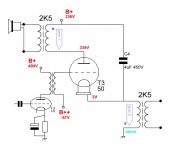
I'm guessing this is the hookup you are referencing.
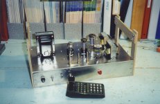
Did this one in 1999 as a way to drive a 600 ohm line.
The OPT in the experiment is a no name UL thing, the output tap off is on of the UL connexions. To do this properly would need a gapped OPT. But what I had worked for the test. The tube used was a triode connected 6K6. In the cct it sees 12K.
For half of the twin coupled mode the bootstrapping comes off the cathode.
Attachments
Yes, precisely.
Except that one wouldn't normally find two separate primary windings on the same core.
A long complaint of mine is that the usual OT manufacturers don't provide separate wiring for the two halves of a P-P primary.
I once requested Edcor to make a P-P OT with separate wires for the center points, and when it arrived it had two wires, both connected to the center tap.
Last edited:
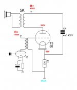
In this example the two 2K5 primaries & loudspeaker secondary are on the same core. So a large DC component, the OPT needs to be gapped.
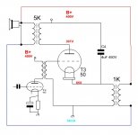
As the load is now equal in anode and cathode, I'd say half the usual anode primary impedance is needed for each. Correct? Of course, a push pull OT with seperated primary terminals would be more economical. I have a few of those... but I wonder if primary inductance will be high enough. Cathode decoupling can be left out I guess. No, it can't. Hahah.
Attachments
Last edited:
That will work if you would like to try. But the low frequencies will be adversely affected because of OPT core saturation. To operate properly, needs OPT core to be constructed, same as for SE.
What you said, if both transformers share the same core, currents will cancel if equally opposite.
Last edited:
Nominally, one would be using two equal turn (or equal primary Z) SE OTs to get the maximum benefit of doubling the effective primary Z. The cores for both need to be gapped to handle the DC flux. (I only mentioned the split P-P case for other purposes, like unusual N Fdbks or current monitoring)
The equal Z OTs make for 50% CFB au-naturale. But using a bootstrap load R on the driver tube can effectively lower the CFB effect and the drive difficulty. A bootstrapped pentode driver would eliminate almost entirely the CFB effect, while a triode driver can be arranged (depending on plate Rp) to null out some portion of the CFB. 10% CFB could readily be achieved that way. McIntosh used a bootstrapped triode driver to preserve some CFB effect in their Unity Coupled amplifiers.
One could also just use a lower Zpri SE OT for the cathode winding side if they just want low CFB %.
The bootstrapped driver tube does still have to handle the large voltage swing for 50% CFB, but the bootstrapping means it does not have to do hardly any gm x Vin activity. So a HV plate rated driver tube is called for still, but high gm not necessarily.
Re: disco
The cathode and plate currents are unfortunately still in the same magnetic polarity when on the same core, so air gapping is still required for the combined winding SE version to handle the DC.
A P-P Twin Coupled does not need the gaps of course.
Last edited:
"P-P Twin Coupled" does not sound familiar to me, you mean a regular push pull OT? The cathode here still needs decoupling for a proper bias, isn't it? It's only 3% (2V/67V) but for exact cancellation it would probably matter...The cathode and plate currents are unfortunately still in the same magnetic polarity when on the same core, so air gapping is still required for the combined winding SE version to handle the DC.
A P-P Twin Coupled does not need the gaps of course.
Attachments
Last edited:
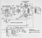
P-P, ie Push-Pull Twin Coupled design, originally by Norman Crowhurst is the standard "Twin Coupled" amplifier design. See schematic below. 2nd pic is a Twin Coupled 6LU8 design by JHStewart9 himself, published in Glass Audio magazine I think. These use ordinary non-gapped P-P OTs.
The grid-cathode does still need proper bias, several ways to set that up.
There is no DC cancellation in the SE Twin Coupled case. Still needs gapped OTs.
The grid-cathode does still need proper bias, several ways to set that up.
There is no DC cancellation in the SE Twin Coupled case. Still needs gapped OTs.
Attachments
Last edited:
It just doubles the power rating of the SE OT effectively.
You can't just double the xformer or tube rating with a circuit trick, that is nonsense.
If this simple fact is not understood here, if people do not understand that if it looks that way, there must be an error somewhere, that's a sad state of affairs.
Jan
You can't just double the xformer or tube rating with a circuit trick, that is nonsense.
If this simple fact is not understood here, if people do not understand that if it looks that way, there must be an error somewhere, that's a sad state of affairs.
Jan
interesting, care to expound why?
- Home
- Amplifiers
- Tubes / Valves
- N. Crowhurst Twin Coupled works for SE too!