Kanwar: I'm sorry, but i'm not sure i understand the essense of this question, could you expand?
Everybody: Happy New Year !!!
Everybody: Happy New Year !!!
@all !
Yes i wish you all a Happy New Year too !!!
Q: how can sells now one or two PSBs to me ?
Lars Clausen said:Everybody: Happy New Year !!!
Yes i wish you all a Happy New Year too !!!
Q: how can sells now one or two PSBs to me ?
Reply
Hi LC_MAN,
The essence is simple.
You have Designed and built the ZETA with your own experience.
But others who have built it may not able to built it in an exact manner as yours. There are several variations involved including PCB Layout etc.
Regards,
kanwar
Lars Clausen said:Kanwar: I'm sorry, but i'm not sure i understand the essense of this question, could you expand?
Everybody: Happy New Year !!!
Hi LC_MAN,
The essence is simple.
You have Designed and built the ZETA with your own experience.
But others who have built it may not able to built it in an exact manner as yours. There are several variations involved including PCB Layout etc.
Regards,
kanwar
Reply
Hi LC_MAN,
Happy New Year!
The essence is simple.
You have Designed and built the ZETA with your own experience.
But others who have built it may not able to built it in an exact manner as yours. There are several variations involved including PCB Layout etc.
Regards,
kanwar
Lars Clausen said:Kanwar: I'm sorry, but i'm not sure i understand the essense of this question, could you expand?
Everybody: Happy New Year !!!
Hi LC_MAN,
Happy New Year!
The essence is simple.
You have Designed and built the ZETA with your own experience.
But others who have built it may not able to built it in an exact manner as yours. There are several variations involved including PCB Layout etc.
Regards,
kanwar
Hi Ampman ,
We all have built the zeta in our own way , but the basic is the same as designed by lars , we cannot get drastic differences in performances unless someone does a really messy job .
cheers
rajeev
We all have built the zeta in our own way , but the basic is the same as designed by lars , we cannot get drastic differences in performances unless someone does a really messy job .
cheers
rajeev
Hi!
A very Happy New year to all.
Rajiv I am very much impressed by your handywork on the Zeta PCB. I would be obliged if you will send me a line diagram / interconnect layout , I wish to design a PCB for all, A Rajiv version. Your layout seems highly suitable for a single sided PCB that can be easily made everywhere in our country.
lorahul@yahoo.com vu3wjm@yahoo.com
Kanwar boss why this change ?????

Hope all well with the com. Anyway I am sure Rajiv might be busy giving your MOSFET designs a try too. Hoping he has recieved the boards and details.
I am sure the com has designed some revolutionary amps how abt just giving us a peek into some old discontinued designs given that the comp was was one the very few pro amp manufacturers in our country.
Regards
Rahul
A very Happy New year to all.
Rajiv I am very much impressed by your handywork on the Zeta PCB. I would be obliged if you will send me a line diagram / interconnect layout , I wish to design a PCB for all, A Rajiv version. Your layout seems highly suitable for a single sided PCB that can be easily made everywhere in our country.
lorahul@yahoo.com vu3wjm@yahoo.com
Kanwar boss why this change ?????
Hope all well with the com. Anyway I am sure Rajiv might be busy giving your MOSFET designs a try too. Hoping he has recieved the boards and details.
I am sure the com has designed some revolutionary amps how abt just giving us a peek into some old discontinued designs given that the comp was was one the very few pro amp manufacturers in our country.
Regards
Rahul
The essence is simple.
Ok you havent experienced this because you have designed it, but what about others who designed your ZETA and encounter breakdowns due to spikes.
My friend I realy need to know more how I can just prevent great damage spike elsewise just by PCB layout alone given that we take all due care in its layout.
Regards
Rahul
To my best knowledge the only problem here is the MOSFET being killed by static electricity BEFORE it is mounted in the amplifier. That would also be the biggest problem associated with using MOSFET in diy power amplifiers. Extreme care should be taken to not get spikes from SE on the Gate. For example using a shorting wire from G to S (or all 3 terminals) until the MOSFET is securely connected in the circuit.
Once the MOSFET is in the amplifier, the circuit protects it against this kind of threat.
btw. last night i played a lot of high power Goa music (i don't know if you guys from India also call it that) about 400 Watts in 4 Ohms on a single pair of IRFP260. It got hot surely, but worked perfectly all along 🙂
At no point became thermally unstable or displayed any other problem.
Static elect is not at all a problem in S India, I have nearly 10 years experience playing with them Some small <1amp devices,large Hexfets and modules and not a single instance of damaged mosfets,,the large capacitance between gate and source Cgs works as an intergrator for high impedance statics.
However in some areas all static prec has to be taken as adviced by manufactures..
GoodLuck 2 all
Sivanand
However in some areas all static prec has to be taken as adviced by manufactures..
GoodLuck 2 all
Sivanand
I don't care if it is 98% humidity where you are, a wrist strap and a grounded iron are MANDATORY.
Fully assembled units are not proof against static unless installed in a metal enclosure and have shorting plugs installed on all input and output jacks.
Even small signal BJTs are subject to damage.
We build avionics and have to take a four hour refresher class on ESD every year.
Fully assembled units are not proof against static unless installed in a metal enclosure and have shorting plugs installed on all input and output jacks.
Even small signal BJTs are subject to damage.
We build avionics and have to take a four hour refresher class on ESD every year.
Reply
Hi everybody,
Rahul glad to see you, happy new Year to you.
The PCB layout has a great influence regarding the spikes, long length tracks between gates of mosfet and driver transistor exhibit parasitic inductances as well as capacitances which inherently tends to generate voltage spikes between these traces.
Hope you understand
Regards
kanwar
long length tracks between gates of mosfet and driver transistor exhibit parasitic inductances as well as capacitances which inherently tends to generate voltage spikes between these traces.
Hi! Kanwar
Right abt long gate leads. I have made many FET amps working upto 50Mhz and beyond (MRF150)) and extra care needs to be taken but Rajeevs layout I dont think suffers from it.
Regards
Rahul
Reply
hi Rahul,
I havent yet seen the Rajeev 's amp from close look, maybe he has mounted the mosfet OFF-board and the gate connecting wires are long, which inturn causes the spikes.
regards,
Kanwar
Rahul said:
Hi! Kanwar
Right abt long gate leads. I have made many FET amps working upto 50Mhz and beyond (MRF150)) and extra care needs to be taken but Rajeevs layout I dont think suffers from it.
Regards
Rahul
hi Rahul,
I havent yet seen the Rajeev 's amp from close look, maybe he has mounted the mosfet OFF-board and the gate connecting wires are long, which inturn causes the spikes.
regards,
Kanwar
Ampman
The gate connections in the pcb I have made are as short as possible and the 100ohm resistor also ends at the gate with very short leads , but this is in the version with two pairs of op devices ,
the gate connections in the version with 10pairs of op devices will be definately longer
and here is where I want to know results of those who have made this version ,
I also see that Mr Holton is using 10pairs of op devices in the complementry version and here it is working with long track to the gates.
Lars,
You will also enjoy the Bhangra beat from ampman,s land . Ampman Please send some Bhangra music to Lars .
Great 400w with a single pair of IRFP260s , When are you going to make the Zeta with 6pairs of parellel devices ?
Regards
Rajeev
amp_man: In theory you are of course right about the parasitic inductances of the gate wire. However the 100 Ohms gate resistor should be able to both dampen the q of this inductance, and furthermore to filter out any short spikes in conjuctuions with 'the large capacitance between gate and source Cgs'.
Personally i have only fried one ZETA module, whilst playing with this output setup. (For hours and hours). And that was owing to poor thermal connection to the heat sink. Apart from that the circuit has survived every attempt from my side, with no problem at all.
🙂 Lars
Personally i have only fried one ZETA module, whilst playing with this output setup. (For hours and hours). And that was owing to poor thermal connection to the heat sink. Apart from that the circuit has survived every attempt from my side, with no problem at all.
🙂 Lars
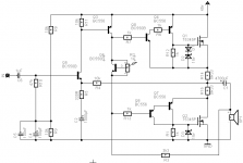
Here is my amplifier I designed a while ago, I didn't build it yet but it should work 😉
I used local feedback to make the mosfets behave somewhat like normal transistors, at least for the voltage they need to turn on.
R6, R7 and R13 are there to stop the transistors from blowing up when the fets run out of voltage.
The reason I designed this amp is because I want to make 4 bi-amped active loudspeakers and I can get these fets for 10 eurocents each 😎
The only downside is they are 55 volts 🙁 but 75 amps 😀
Attachments
- Home
- Amplifiers
- Solid State
- N-Channel mosfet amplifier schematic needed