If the mosfets are taken arbitrary, they aren't matched, eg. one have Vgs of 3V, the other have Vgs 3.7V, the 3Vgs mosfet will always work heavily, and the other maybe off most of the time.
Except you make classD, where the condition is only on and off, it doesn't need matching. Source resistor is a simple but effective way to make sure sharing current between output mosfets. It's also a cheap solution. Why want to omit that?
Except you make classD, where the condition is only on and off, it doesn't need matching. Source resistor is a simple but effective way to make sure sharing current between output mosfets. It's also a cheap solution. Why want to omit that?
Firstly, ampman always stresses the importance of matching Vgs of MOSFETs. The source resistors don't actually address the Vgs issue, they only ensure thermal stability by compensating for the positive temperature coefficient when only an amp or so is passed. However, as ampman points out, at high currents the characteristic naturally changes to that of a negative tempco. So you can see in ampman's case where the amps are run flat out, there is no need for source resistors.
Hi, Richie00boy,
I'm not very good at electronics, but I read somewhere that the so called "negative tempco" at Vertical mosfet is not practical for advoiding thermal compensation or eliminting Source Resistor. It happens at a VERY HOT temperature (far more hot than ordinary operational temperature of audio amplifier). Therefore, we cannot depend on negative tempco at audio Vmosfet amplifier cct. At ordinary average audio amplifer's working temperature, the Vmosfets still exhibit positive tempco.
If the Ampman's factory always uses matched mosfets, will his customer (or his customer's repair-technician) will know about this, and not use arbitrary mosfet (even with the same type) they can buy at their local electronic market? It's making things complicated for business and after sales service.
You are right that the tempco changeover is at high current and this level will probably not be reached in domestic situations. However, as I said, in ampman's world of pro environment things are run right up to the max.
Again, reiterating what I said before, source resistors do not address the Vgs mismatch issue, only the thermal issue. There is no alternative (other than individual, complex, loop feedback/remote current sensing circuitry) to using matched banks of devices when using many devices *and* getting the max from them.
In the totally unlikely event that a single device fails in a bank, and that is replaced with a random same device type, if the Vgs is higher than the rest it will simply conduct less. Adding a source resistor will not make it conduct the same as the others as the voltage applied to gate is not changed (relatively speaking) in fact it will actually be a little less as the source will be 'lifted' slightly. This is the opposite of what we want. The feedback obtained using source resistors is always relative to it's gate-source voltage, trying to maintain it's *original* condition. If the device heats up and flows more current, the voltage across the source resistor will increase and reduce the voltage between gate and source (as the gate is held fixed and the source rises), turning it off a little thus ensuring stability. Hence if in the original condition the device does not 'know' that it should conduct more to keep up with the rest, it will not conduct more.
In a nutshell, because the source resistors only give feedback about the *individual* device and there is no way of an individual device knowing what the other devices are doing, source resistors will do nothing for current sharing due to Vgs.
However, mismatched devices can survive in real life as long as everything is run well within it's bounds, which seems to be how designs using random devices succeed.
If ampman chooses to run his business so that the amp must be returned for service, that is his choosing. To his advantage it will allow him to do more with less, hence can be more competitive in price/smaller size.
Some Serious Comments
Hi Guys,
Rajeev Luthera, LumanauW ,
Look Guys WhY I dont use Source resistors with V-MOSFETSis Because they simply doesnt do any thing in relation to CURRENT SHARING , THERMAL RUNAWAY PROTECTION etc.
I AM SAYING THIS BECAUSE I HAVE DONE LOTS OF EXPERIMENTATION DURING FIELD TESTING IN PRO ENVIRONMENT WITH AMBIENT TEMP OF SURROUNDINGS AT 45DEG CELCIUS.
We Even Tested the amps with Totally mismatched Mosfets But The Result was same , Nothing Terrible Happens .
ThanX to Positive Temp Coeff.
Therefore I DONT CARE if ANYone uses them or not in thier amps.
But I will not use them at any cost because they their contribution is NILL.
WE EXCLUSIVELY THANX
RITCHIE BOY '
FOR HIS LOGICABLE STATEMENTS ABOUT OUR CRITERIA FOR NOT USING SOURCE RESISTORS.
Hope That it will Clear ur Minds for any Doubts
Attachments
Hi, Richie00boy,
Ampman,
How do you know that your amp will always used at its max? Even amp in discotheque (Crest 9001 or Crown BCA) will take a rest between bass hits. Or is it you are making ClassD amp, not classAB, that the output mosfets are always working max?
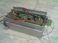
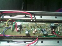
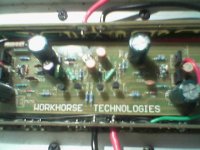
Anyway, nice amp you make. Some years ago, I make this for heavy working amp. I use 10pairs MAT-200 dies for each channel. The heavy current path is stiffed with copper bars. The heatsinks are blown with temperature controled cooling fan. And it still pumping power now 😀
Yep, that's the mechanicsm of the advantage of Rsource in using random Vmosfets 😀If the device heats up and flows more current, the voltage across the source resistor will increase and reduce the voltage between gate and source (as the gate is held fixed and the source rises), turning it off a little thus ensuring stability.
Yep, yep, if you put enormous number of output device for a certain rating, it will be alot more safer to breakdown. But not so economical for the producer, though.However, mismatched devices can survive in real life as long as everything is run well within it's bounds, which seems to be how designs using random devices succeed.
Ampman,
How do you know that your amp will always used at its max? Even amp in discotheque (Crest 9001 or Crown BCA) will take a rest between bass hits. Or is it you are making ClassD amp, not classAB, that the output mosfets are always working max?
Anyway, nice amp you make. Some years ago, I make this for heavy working amp. I use 10pairs MAT-200 dies for each channel. The heavy current path is stiffed with copper bars. The heatsinks are blown with temperature controled cooling fan. And it still pumping power now 😀
Attachments
Commentable Experienced Thoughts
LumanauW
Every Music has a Bit of Resting period in between But this doenst mean that the amp is resting for a long time.
In our Country people dont use a 2000W amp for just upto 500W output, Inspite they tend to overload them and the Temp outside is also at 45Deg C average.
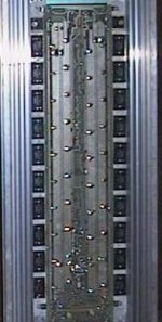
our 1800W amp uses 32 mosfets [16 Per channel]
With Force cooling with Constant AC mains Voltage Fans
Regards
ampman
LumanauW
Every Music has a Bit of Resting period in between But this doenst mean that the amp is resting for a long time.
In our Country people dont use a 2000W amp for just upto 500W output, Inspite they tend to overload them and the Temp outside is also at 45Deg C average.
our 1800W amp uses 32 mosfets [16 Per channel]
With Force cooling with Constant AC mains Voltage Fans
Regards
ampman
Thank you all for this very interesting discussion. Of course losing the source resistors would be of great interest, because they take up a lot of space on the PCB. I have given this possibility a lot of thought. And maybe if i was to produce this amplifier in house, i would consider it. Because then you have full control over the devices used. However ...
As we have seen in this thread when it is a DIY amplifier people will use all sorts of MOSFET's they have in the drawer. Not nessecarily the types stated in the schematic. And maybe different types for upper and lower rail.
This is why in my opinion the source resistors will at least increase the amplifier's robustness towards using different MOSFET's in parallel. Of course this is particularly important when operating at high voltages, as the differences in Vgs will cause greater differences in Ploss.
But maybe amp_man is right, that it will work fine anyway. At this point i am not prepared to jump for that chance though, at the risk of losing some of the reliability.
EDIT: the resting period of most music types is 65-70%, but since a class A amplifier has a very low efficiency at below max. power it will still dissipate as much power from 20% up as at full power. (About 60% of full power).
Also i would hate the idea of having to match all the MOSFET's just to keep the amplifier reliable.
Another thing is that in the event of a burnout you could replace the defective MOSFET with another date code or make. I think this problem is not relevant because in that event you should definitely replace all output devices, or even the entire PC board, to keep your amplifier 100% reliable.
As we have seen in this thread when it is a DIY amplifier people will use all sorts of MOSFET's they have in the drawer. Not nessecarily the types stated in the schematic. And maybe different types for upper and lower rail.
as what I have done in one channel of my zeta...... I used IRFP460 in the upper rail and IRFP254 in the lower rail. I ran out of output devices but I'm not having trouble with this one.
Hi, LC,
Zeta is a good design (for DIY comunity) because you have taken tought of that "Non-electronic" considerations that may happen to all who built it. "Non-electronic" here like not complicated cct, easy to get components, easiness of service, etc, and still pumping up power . Good for you.
(You will make a good "military standar" fabricator. What happens if an army is in the middle of the jungle and cannot fix his own jeep with anything he can reach?)
Other design, while looks better in the paper, but needs matched device, problematic maintenance, is not considered practical good DIY design. Even if sold commercially, if the after sales service is problematic (like the buyer is in Australia, for service he has to ship the whole unit to Denmark that cost $$$$ for airfreight heavy amps, usually that customer will not buy that product again).
Ampman,
I have a question that I cannot answer myself, so I need your Very Serious And Experienced comment. Why is it in parrareled mosfet final stages, they seldom broke down single transistor, always broke the whole array? How to advoid that?
Hello ,
I have etched and drilled the pcb for the zeta and have mounted most of
the components , now only the mosfets are to be connected I will give my
report in a day or two . I have used 470 ohms instead of 499 ohms and
220 ohms instread of 200 ohms I hope this will not matter .
I wonder who else has attempted to make the ZETA other than Dj Quan
and me , please those who have made this amp kindly post your
experiance .
HI ALL
I have finally completed the amp , It is working since last one hour on my
work bench , it sounds more like a valve amp , very clean sound , good
bass too , I only tested with input from a cd player at about 15watts
output , I will give it the works only after I properly mount it in a chasis , at
present I could not wait so I powerered it up , first I only used two
output devices in the complementry mode and in the first attempt it
worked fine , I would say that those who want 100w or less power they
should go for complementry output , T14 & T15 are enough ,
then I changed it to the n- channel version and it is doing fine with n-
channel mosfets in the output ,
Lars
I would like to thank you for the project and all the help you are giving to
everybody ,
a few questions ,
1, the quesent current is a little higher in in the +ve rail than the negetive .
2, I have as yet not added the offset null preset but I will do it now as the
offset voltage is a little high 65mv ,
3,regarding the value of R in the drain of T14 irfp9240 , how to select the
most optimum value ??
4, what is the meaning of THE ZETA
Ampman
Thanks for all the feedback from your reserch , I am always learning from
you pro guys !!!!
Commentable Experienced Thoughts
LumanauW
Acc to our experience with our designs, we have encountered only damage due to excessive clipping , which increases the gate threshold voltage limits of mosfets , to protect these from overdrive we use inverse parallel 12V 1 W Zeners. And we also employ a LIMITER circuit which restricts the input signal value to safe limits , i.e. belao clipping.
As the gate voltage exceeds for all parallel devices, so how a single device could be damaged alone therefore all the devices damaged at this condition.
We havent yet encountered any damage due to thermal overheating , So no comments on it.
Neither we have encountered any problems regarding short circuiting because our protection circuit is very robust and it protects the mosfets in terms of short circuit condition.
Acc to what we have experienced with mosfets are that they are Virtually indestructable than Bipolars.
Hi Rajeev
Accept our heartiest Congratulations on ur completion of ZETA amp.
Yeah we r pro-guys becos we r PROFESSIONALS
regards
ampman
lumanauw said:Hi, LC,
Ampman,
I have a question that I cannot answer myself, so I need your Very Serious And Experienced comment. Why is it in parrareled mosfet final stages, they seldom broke down single transistor, always broke the whole array? How to advoid that?
LumanauW
Acc to our experience with our designs, we have encountered only damage due to excessive clipping , which increases the gate threshold voltage limits of mosfets , to protect these from overdrive we use inverse parallel 12V 1 W Zeners. And we also employ a LIMITER circuit which restricts the input signal value to safe limits , i.e. belao clipping.
As the gate voltage exceeds for all parallel devices, so how a single device could be damaged alone therefore all the devices damaged at this condition.
We havent yet encountered any damage due to thermal overheating , So no comments on it.
Neither we have encountered any problems regarding short circuiting because our protection circuit is very robust and it protects the mosfets in terms of short circuit condition.
Acc to what we have experienced with mosfets are that they are Virtually indestructable than Bipolars.
rajeev luthra said:HI ALL
Ampman
Thanks for all the feedback from your reserch , I am always learning from
you pro guys !!!!
Hi Rajeev
Accept our heartiest Congratulations on ur completion of ZETA amp.
Yeah we r pro-guys becos we r PROFESSIONALS
regards
ampman
Ampman,
Yeah, thats the answer. Thanks for your Very Experienced and Very Serious answer. 😀
But I wonder why I rarely see this gate protection in classD amps? The mosfets here are always working in saturated mode. What do you think makes failure in classD output mosfets?
Robustness is very important in pro-amps. Have you seen the service manual for Crest 8001? They have good auto-gain controller to advoid clipping by sensing the output, then put back to the front end. It's a clever active prevention.
Output current limiter usually lies on Rsource. Since you don't use Rsource, where do you put the sensing device for over-loaded protection? You put R in your supply rail?
Commentable Experienced Thoughts
Hi LumanauW
Acc to our experience in Beta[R & D still Going on]Class-D amps output device damage is due to
Cross-Conduction [Not enough Deadtime]
Reverse spikes originating from Back EmF of Inductor Filter
gate overdriven
Bootstrap Cpacitor not choosen Adequately.
I have seen almost every pro amp in the world , not only service manuals but also in real world.
Crest uses auto gain to avoid ABRUPT turn ON to safe guard the output devices from INSTANTANEOUS Stress during power failure -> To sudden back on. They have employed a current sensing resistor in series with load to carry on this task.
We have something different.
We employ a FET emulated as resistor on input which slowly increase the signal level in 2-3 Seconds to previous settled mode, thus prevents stressfull conditions during Abrupt turn on.
Yeah we use R Sense resistor on Supply Rails to detect short Circuit or overcurrent.
For DC fault Protection We use Traic Crowbar
#######################################
We r not alone in the world to use Mosfet without Source resistors. Visit This site to see K6 amp schematic to confirm about it. www.a-and-t-labs.com they also use mosfets without source resistors.
############################################
Hope that it helps
lumanauw said:Ampman,
Yeah, thats the answer. Thanks for your Very Experienced and Very Serious answer. 😀
But I wonder why I rarely see this gate protection in classD amps? The mosfets here are always working in saturated mode. What do you think makes failure in classD output mosfets?
Robustness is very important in pro-amps. Have you seen the service manual for Crest 8001? They have good auto-gain controller to advoid clipping by sensing the output, then put back to the front end. It's a clever active prevention.
Output current limiter usually lies on Rsource. Since you don't use Rsource, where do you put the sensing device for over-loaded protection? You put R in your supply rail?
Hi LumanauW
Acc to our experience in Beta[R & D still Going on]Class-D amps output device damage is due to
Cross-Conduction [Not enough Deadtime]
Reverse spikes originating from Back EmF of Inductor Filter
gate overdriven
Bootstrap Cpacitor not choosen Adequately.
I have seen almost every pro amp in the world , not only service manuals but also in real world.
Crest uses auto gain to avoid ABRUPT turn ON to safe guard the output devices from INSTANTANEOUS Stress during power failure -> To sudden back on. They have employed a current sensing resistor in series with load to carry on this task.
We have something different.
We employ a FET emulated as resistor on input which slowly increase the signal level in 2-3 Seconds to previous settled mode, thus prevents stressfull conditions during Abrupt turn on.
Yeah we use R Sense resistor on Supply Rails to detect short Circuit or overcurrent.
For DC fault Protection We use Traic Crowbar
#######################################
We r not alone in the world to use Mosfet without Source resistors. Visit This site to see K6 amp schematic to confirm about it. www.a-and-t-labs.com they also use mosfets without source resistors.
############################################
Hope that it helps
Attachments
AMP PROTECTION
I may be wrong but I presume the following difference in both types of
protection
When the protection ckt is activated by sensing overcurrent from the
supply rails , it is too late to save some devices while if the same is
activated by sensing overcurrent from the source resistor of each device
, you do have a chance to save other devices in case only one or two
have failed .
To avoid premature tripping the protection ckt is given a margin after
which it will tripp , now if the Zeta takes 6A from a supply of +/- 90v to
deliver 800w power the protection will be set to activate say at about 8 to
9A or even higher current, similarly if the detection is from the source
resistor the sensing will be overcurrent of ONLY THE DEFECTIVE
DEVICE which is one tenth of the total current ( in case 10 pairs of
output devices are used ) hence the amp will be switched off eirlear thus
saving the other devices .
I have lowered the DC offset somewhat by half. I reduced the feedback resistors from 100k to 20k and 1k to 383R. so I have -400mV left. (-200mV on the other channel.)
any ideas? I replaced the dubious looking TIP32 devices and tested for hfe. still, no effect.
any ideas? I replaced the dubious looking TIP32 devices and tested for hfe. still, no effect.
Commentable Experienced Thoughts
RajeeV Hi,
this not True for Mosfets because they are Voltage driven devices in which conduction current is controlled by gate voltage therefore the voltage at the time of Short will be same for all devices therefore the conduction will be similar due to realworld discretion effects, hence the total current will be used for sensing the short circuit on power rails
Since there is also another way of sensing short which senses the gate voltage drive, if it exceeds the specified limit then it trips or mute the input signal.
Hope u understand
rajeev luthra said:AMP PROTECTION
I may be wrong but I presume the following difference in both types of
protection
When the protection ckt is activated by sensing overcurrent from the
supply rails , it is too late to save some devices while if the same is
activated by sensing overcurrent from the source resistor of each device
, you do have a chance to save other devices in case only one or two
have failed .
To avoid premature tripping the protection ckt is given a margin after
which it will tripp , now if the Zeta takes 6A from a supply of +/- 90v to
deliver 800w power the protection will be set to activate say at about 8 to
9A or even higher current, similarly if the detection is from the source
resistor the sensing will be overcurrent of ONLY THE DEFECTIVE
DEVICE which is one tenth of the total current ( in case 10 pairs of
output devices are used ) hence the amp will be switched off eirlear thus
saving the other devices .
RajeeV Hi,
this not True for Mosfets because they are Voltage driven devices in which conduction current is controlled by gate voltage therefore the voltage at the time of Short will be same for all devices therefore the conduction will be similar due to realworld discretion effects, hence the total current will be used for sensing the short circuit on power rails
Since there is also another way of sensing short which senses the gate voltage drive, if it exceeds the specified limit then it trips or mute the input signal.
Hope u understand
- Home
- Amplifiers
- Solid State
- N-Channel mosfet amplifier schematic needed