Sorry about that. My impression is that for some reason the gates became driven with too much voltage and failed. Someone who built amp or anyone, for that matter, may have further or better ideas of what happened.
Member
Joined 2002
realy sparks humm weird i hope min doesnt perform a spark show. im building another of anthonys amps now a pair of av800's
MOOO POWA
MOOO POWA
Member
Joined 2002
More q...
Just another thing...would it be more stable / safer w. a 2 x 60V DC supply?
Can anyone guestimate the output power w. +/- 60V?
Arne K
Just another thing...would it be more stable / safer w. a 2 x 60V DC supply?
Can anyone guestimate the output power w. +/- 60V?
Arne K
Member
Joined 2002
Re: More q...
if you want 100watt/8 ohm
SQR(100x8)x1.4= 40 volt peak = +-40V
80 watt /4ohm
SQR(80x4)x1.4= 25 volt peak
Of course PSU can sag some 5 volts, so you have to add for that,
and some 2 volts for Transistors workspace
[(0.7x60v)^2]/8 ohm= 225 wattCobra2 said:Can anyone guestimate the output power w. +/- 60V?
Arne K
if you want 100watt/8 ohm
SQR(100x8)x1.4= 40 volt peak = +-40V
80 watt /4ohm
SQR(80x4)x1.4= 25 volt peak
Of course PSU can sag some 5 volts, so you have to add for that,
and some 2 volts for Transistors workspace
Cobra2
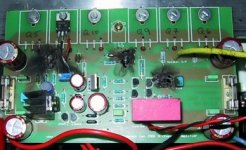
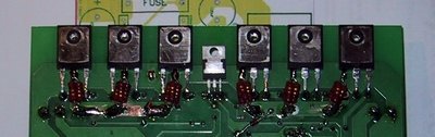
You have mounted the IRF610 Thermal sencing device incorrectly to the o/p stage. Mounting it on top of the PCB like you have done is very bad and you can see the result.
It must be in direct contact with the top of the o/p device and I see you haven't added the Source resistors or the rest of the manatory upgrades, that this amplifier requires for thermal stability.
Please read the manual again, its all in the construction manual.
Regards
Anthony Holton
www.aussieamplifiers.com
Member
Joined 2002
anthony my amp is looking difrent now the reisters that you told me to put on are on now that pic that i posted was just a pic just because ihad a pic of what i had done so far a whyle back. also humm if these transisters have to be mounted ontop of the fet then why did you design it this way..?
cant i mount the fet to the heat sink. the irf610 the bias one. ? the one that controles the bias from heat.
?
cant i mount the fet to the heat sink. the irf610 the bias one. ? the one that controles the bias from heat.
?
Member
Joined 2002

Jason That photo of my amp is an old one as well. However it does have the thermal sencing device mounted on top of one of the fets.
Mounting on the heat sink will work OK, but don't increase the rail voltage. The Gate theshold voltage at higher supply voltages just gets to much out of control, without further modification of the thermal tracking senser.
Anthony
Mounting on the heat sink will work OK, but don't increase the rail voltage. The Gate theshold voltage at higher supply voltages just gets to much out of control, without further modification of the thermal tracking senser.
Anthony
Member
Joined 2002
Member
Joined 2002
i cant wait till my av800'sare here and start plunkin parts onto them YEAH power
b.c hydro is going to love me..
: O )
b.c hydro is going to love me..
: O )
Member
Joined 2002
well actualy longer than that ebcause there going to anthony not me : O ) but ill get my next parts shipment from him with the boards eeh
just ordered heatsinks for my aleph 2's yeah.. now to start saving for toroidals
i need 4 x 1 kva 2 for av800's and 2 for alephs there is $500.00 right there.: O ) man this bhobbie is expencive.
J'
just ordered heatsinks for my aleph 2's yeah.. now to start saving for toroidals
i need 4 x 1 kva 2 for av800's and 2 for alephs there is $500.00 right there.: O ) man this bhobbie is expencive.
J'
here we go...
How do we adjust bias without resistors (ref. the assembly-instructions).
Anyway, I must have misunderstood an earlier post where +/- 95V DC were mentioned, with some other mosfets, - (so I thought that it would be them living dangerous).
Glad I have spare PCB's, finished, all resistors matched to ~0,2%...
I'll just have to redesign PSU, and make better thermal coupling before I try again.
Arne K
Attachments
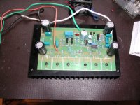
Working!
N-channel, the sequel...
The previous experiment also killed all(!) the 0,33 Ohm (3 x 1 ohm-2W) resistors as well.
So some adjustments had to be done:
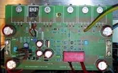
2 x New trafos, 2 x 38V gives me +/-55V DC,...updated "modified" PCB, (hacked out for thermal coupling of Q12).
Now everything seems stable.
Arne K😀
N-channel, the sequel...
The previous experiment also killed all(!) the 0,33 Ohm (3 x 1 ohm-2W) resistors as well.
So some adjustments had to be done:
2 x New trafos, 2 x 38V gives me +/-55V DC,...updated "modified" PCB, (hacked out for thermal coupling of Q12).
Now everything seems stable.
Arne K😀
Attachments
Some time ago I aked for any measurement. Does anybody performed them ( THD, spectral analysis, S/N, or so)? Even using PC sound card.
I can do THD analysis...
-If you will throw me some high-power load resistors...
Sound-vice, you do not need to worry about distortion.
It sounds very clean (and silent), with a strong and powerful bass. Very well controlled.
I think I will give it a 96% score against my14 year old Dynamic Precision Amp, ( 2 x 250W Class A), maybe a 115% score in bass area, (probably caused by dried up caps in my old amp).
(BTW, I use 2 x 500VA trafos (dual mono) and 44 000uF pr.rail, total 176 000uF)
Arne K
NORWAY
(Can hardly wait to start building Aleph 2, for bi-amping...)
😉
- Status
- Not open for further replies.
- Home
- Amplifiers
- Solid State
- N-channel amp.