I read that as saying that when you decrease signal levels towards zero, distortion goes to zero.
What you describe is the ac small signal simulation in a circuit simulator, linearize the device around the bias point to get the frequency domain response.
But it is totally useless (and really nonsensical) for transient/large signal analysis.
I did some testing on I/V networks to get a feel for the possible mechanisms that might be responsible for sonic differences. This involved subjecting I/V networks with up to +/- 8mA full scale switching currents and up to a 4MHz switching rates (2MHz square wave currents).
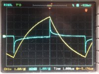
The 1.JPG screenshot below shows an output signal in yellow in relation to the difference signal between the input terminals (illustrated in white), Difference signals were amplified x100 before feeding to the oscilloscope. It should be noted that the oscilloscope scales are the same, hence the input difference signals are actually 100x smaller than that of the output. The network employed an NE5534 op-amp to implement the
I/V with 2K Ohm feedback resistor paralleled with I believe 820pF capacitor. The input signal was set for a +/- 2mA square wave. seemingly at 100KHz from the scales.
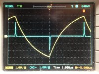
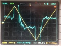
For comparison, I believe 2.JPG is that of a compensated AD844 in a feedback arrangement also containing a feedback capacitor (the AD811 implementation by Walter Jung is also compensated to support a feedback capacitor). 3.JPG screenshot is a further 10x magnification of the input difference voltage, that I believe represents a dynamic input impedance reducing to around 0.1 Ohm in 300 nSec after a transient.
The point I was trying to make was that problematic areas can be more easily locatable in the observation of the input difference signals in the time domain. The higher magnitude differences (the transients) impose themselves on a greater portion of a non-linear transfer curve than when things return to a new steady state current level. For example in 2.JPG it can be speculated that the curvature in the output is likely a more accurate reflection of the RC feedback network alone than that of 1.JPG (the curvature of the waveform seems a little straighter for awhile after the transient). Note that these do not reflect output loading that could dramatically affect performance.


Ahh yes - good catch. To late for the publication, but good to know for the next. Thanks!It's microseconds (μs), not microsiemens (μS) 🤓
Jan
I bought one for the lifetime guarantee. It was used it in a vertical particle levitator requiring a resonant column where the interface between the compression / rarefaction layers could suspend solid particles.maybe a Bryston 4-B amp...
The column was driven by a high Q resonant plate set to about 19KHz in a phase lock arrangement. Because the phasing flipped over more than a cycle this required a close adjustment near the resonant frequency before flipping on the phase lock loop. It went off like a laser and saw the immediate demise of many a lesser amplifier not covered by a warranty. A testament to unconditional stability.
A quick thought is that I have learned to limit the bandwidth of everything I design with input filters. Limiting the bass (with a higher order active filter) really cleans things up a whole lot, and not just for the electronics. You can drive speakers a whole lot harder. And 159 kHz is the high frequency limit.
It really increases complexity and cost, and is maybe not cost effective for commercial designs. But this is custom stuff so who cares?
Jan, you wrote:
Where does that ''tau of 3μs'' come from? That ought to be 3x tau for 95% of the signal level then, as the graph correctly shows a level of ''1 tau'' = ~63% at 1μs.
I specified an exponential input source pulse signal to LTspice as EXP(0 1 0 50µ 1µ), which means a signal that starts at 0V at time zero, then exponentially rises to 1V with a τ (RC time constant) of 3µS, stays there for 50µS then falls at the same rate (not shown).
Where does that ''tau of 3μs'' come from? That ought to be 3x tau for 95% of the signal level then, as the graph correctly shows a level of ''1 tau'' = ~63% at 1μs.
Back to feedback and loopgain (feedback factor) and yes with regard to time domain discussion - though I agree that very high loopgain and advanced compensation schemes like 2-pole, TMC, TPC do grossly decrease high frequency non-linear distortion, I doubt it is necessary re audibility. It is a two edged sword. Though in simulation a loopgain stability may seem sufficient, in a real-life amplifier there may be stability issues that are more pronounced and more dangerous in case of high HF loopgain wide bandwidth circuits. I am collecting and classifying data and will start a new thread, this one is intended to be a "general" one.
I get away from the problem by saying uSec for the time interval. If I use upper or lower case 's' in that, the meaning will still come across.Ahh yes - good catch. To late for the publication, but good to know for the next. Thanks!
Jan
Except second is not a proper noun and isn't capitalized (outside of programming language name conventions).
Its "microsecond" or "µs" (or "us" if greek letters not available). This is well defined in the S.I. standard.
Its "microsecond" or "µs" (or "us" if greek letters not available). This is well defined in the S.I. standard.
Well people from certain parts of the world have their own idea about standards. 😂😂😂😂This is well defined in the S.I. standard.
Unity gain at DC. AC gain determined by the two resistor values once you're above the knee.
As the two capacitors are what we are essentially listening through , I see Papa tried to solve the mystery of Celephant several years back https://www.diyaudio.com/community/threads/best-electrolytic-capacitors.151392/#post-1919931, what's your preferred choice for Celephant, how many are on tantalum, Mundorf or Elna or other, whats music to your ears?
We seem to be going down the ‘high loop gain’ or ‘wide band loop gain’ or multi-slope comp schemes’ are all troublesome.
These techniques will require optimisation but have been shown to work exceedingly well if treated with respect. The problem comes when people chase vanishingly low distortion as the prime focus of their efforts and then take risks with gain and phase margins, or fail to investigate the secondary loops eg TPC or TMC loops thoroughly.
🙂
As the two capacitors are what we are essentially listening through , I see Papa tried to solve the mystery of Celephant several years back https://www.diyaudio.com/community/threads/best-electrolytic-capacitors.151392/#post-1919931, what's your preferred choice for Celephant, how many are on tantalum, Mundorf or Elna or other, whats music to your ears?
If you want to avoid large capacitors, you can either use a DC bias loop or, in case of a FET input, put a capacitor between a low-resistance voltage divider and the negative input and add a large resistor from the output to the negative input.
- Home
- Design & Build
- Electronic Design
- Myths, tricks and hey, that's neat!