Where do I find kits for MyRefC?
This one I found on eBay and it seems to be a MyRefC:
Classic lines LM3886 dual-channel +LM318 AMP/ DIY | eBay
That's most probably a knockoff of an early MyRef Rev A stereo layout, which had a common protection relay circuit. The bare board from the same seller is probably reasonably good value.
Please PM me for Rev C (monoblock) bare boards and kits.
Hi
dont know about that ebay model?
contact linuxguru on the forum he is supplying the latest incarnation as a board or kit (i think he has two kits premium and standed)
dont know about that ebay model?
contact linuxguru on the forum he is supplying the latest incarnation as a board or kit (i think he has two kits premium and standed)
Where do I find kits for MyRefC?
This one I found on eBay and it seems to be a MyRefC:
Classic lines LM3886 dual-channel +LM318 AMP/ DIY | eBay
Has someone tried it?
Carlos
Yes , it's a MyRefC with a common protection circuit, before last modifications (feedback network)
I bought the same PCB , and I'm in the process a building a 6 channels MyRefC with them.
The PCB quality is good. Don't known about components quality as I bought PCB only...
Hello everyone, I just tested out one of my boards from the group buy and I get a serious amount of hiss with out any input connected. Another strange think I noticed is if I touch the 220uf blackgate I get radio interference. It sounds like I am trying to tune an old AM radio. Anyone have any idea what I messed up?
I would also like to add that if I connect a source to the input it plays loud and clear but at low volumes I can still hear a loud hiss.
I would also like to add that if I connect a source to the input it plays loud and clear but at low volumes I can still hear a loud hiss.
Last edited:
I would also like to add that if I connect a source to the input it plays loud and clear but at low volumes I can still hear a loud hiss.
It's most probably a grounding/shielding issue - check the 1-ohm ground-isolation resistor as well as the shield contact at the input connector blocks. Also check for cracked or dry solder joints in the signal and feedback paths.
I would also like to add that if I connect a source to the input it plays loud and clear but at low volumes I can still hear a loud hiss.
As LinuxGuru already pointed out it seems a grounding problem.
Is PGND connected to safety earth directly or via a thermistor/ground breaker/resistor?
If not, do it.
Without source connected a certain amount of hum is normal but with something connected it should be deadly silent.
Thanks for the suggestions, I checked the 1 ohm resistor and I went over all the solder joints. Then I added a CL60 thermistor between PGND to earth ground. Sadly the hiss is still present.
If I remove the wires from the input connector blocks the hiss goes away. So Im guessing it must be the wires picking up the hiss. I tried 3 different shielded wires from the input to the RCA jack with the same results. One set had foil shielding another set had braided shielding and another set was a monster cable interconnect with heavy shielding that I cut up. I dont get it, I built a pair of twisted pear my ref 2 years ago and I wasnt careful at all with my choice of wires and that set of amps was pretty silent.
If I remove the wires from the input connector blocks the hiss goes away. So Im guessing it must be the wires picking up the hiss. I tried 3 different shielded wires from the input to the RCA jack with the same results. One set had foil shielding another set had braided shielding and another set was a monster cable interconnect with heavy shielding that I cut up. I dont get it, I built a pair of twisted pear my ref 2 years ago and I wasnt careful at all with my choice of wires and that set of amps was pretty silent.
This isnt a hum, its a sound like white noise and its audible from 3 meters away.Without source connected a certain amount of hum is normal but with something connected it should be deadly silent.
Last edited:
Yes , it's a MyRefC with a common protection circuit, before last modifications (feedback network)
I bought the same PCB , and I'm in the process a building a 6 channels MyRefC with them.
The PCB quality is good. Don't known about components quality as I bought PCB only...
Where can I get a schematic with those last modifications?
The eBay photos do not show what's behind capacitors, probably a bridge instead of discrete diodes. If you bought the pcb you can see that. Am I right?
What are you going to feed onto that 6-channel amp you are building?
It's a long time since the original MyRefC project was introduced, so there are a few things I don't remember.
1) Is a buffer necessary as it was on the Gainclone?
2) Has anyone bridged or paralleled two MyRefCs to increase power or current capability?
1) Is a buffer necessary as it was on the Gainclone?
2) Has anyone bridged or paralleled two MyRefCs to increase power or current capability?
Yes , it's a MyRefC with a common protection circuit, before last modifications (feedback network)
I bought the same PCB , and I'm in the process a building a 6 channels MyRefC with them.
The PCB quality is good. Don't known about components quality as I bought PCB only...
Hello, i´m very interested to know your opinion, please comment us when you finish the build

Where can I get a schematic with those last modifications?
Don't remember where I got mine.
Will try to look.
The changes are just :
R2 10K (was 33K) : LM3886 mute
R42 47 was 270
C21 22nf was 100nf
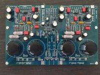
The eBay photos do not show what's behind capacitors, probably a bridge instead of discrete diodes. If you bought the pcb you can see that. Am I right?
Yes a bridge. In fact I plan to feed mines with SMPS, so don't are about this part.
See joint image
What are you going to feed onto that 6-channel amp you are building?
My 3ways multi amplified system.
Attachments
1) Is a buffer necessary as it was on the Gainclone?
2) Has anyone bridged or paralleled two MyRefCs to increase power or current capability?
1) No buffer is needed, the on-board LM318 stage provides sufficiently high input impedance (~100k). However, if you use a passive attenuator before the MyRef, then you may need a buffer, depending on your source impedance.
2) Not recommended - you need additional circuitry, and exactly-matched monoblocks to have a decent shot at success. If you need more power, skip the MyRef and go straight to Mauro's Evolution.
Are there any current sources for either kits or PCBs for the Evolution? It looks to me like it either went commercial or disappeared a few years back.
Headphone output
I am happier day by day with the My Ref Rev C Ultimate I built from last years group buy. Just seems to sound better and better.
Unfortunately not everyone in the house shares my enthusiasm!
So I'm thinking to add headphone output something like this circuit Headphone Adaptor for Power Amplifiers from Elliot Sound Products very useful site (hope it's fine to link to this site, thanks).
Property of Rod Elliott, Copyright © 2003
I am pretty clueless regarding the jargon and don't know what 'bridged' means in reference to amplifiers, there is a warning against using this circuit with a bridged amp. I am thinking the My ref is not bridged? Is that right?
I think I remember the negative speaker terminals are grounded on the my ref but mine is hard to get at (the back of) to check right now.
Does anyone have any input regarding the choice of resistors in terms of effect on sound quality? I am aiming to drive a pair of 32 ohm impedance Grado phones (the budget version).
Any recommendations? Or a redirection to another thread if appropriate?
I know this is not specifically to do with this amp but I am intending to try using this circuit with the my ref rev c ultimate and hoping for a little advice from the wise.
Thanks
Bill
Use an attenuator ladder comprising two resistors for each channel to give your HP output.
The lower resistor can be anything between 1r0 and 100r. The upper resistor is 9times as large for a ~-20dB output. If the upper is raised in value then the attenuation is increased. Alternatively adding a parallel Rlower increases attenuation.
The power amp sees Rupper + [Rlower//Rheadphones] as the load.
I suggest you start with Rupper = 100r and Rlower = 10r.
With maximum output of 60W into 8r0 (~22Vac) the resistors will dissipate ~4.4W.
@ -10dB average listening levels the average dissipation is <500mW.
@-20dB average listening levels the average dissipation is <50mW.
Buy 10 each of 50r & 10r 600mW 1% metal film resistors.
This allows 50r|10r or 50r+50r0r//100r|10r or 50r+50r|10r//10r or 50r+50r|10r//10r//10r combinations for a wide variety of attenuations to suit your phones.
Advice:
forget the word "bridged" was ever invented.
Last edited:
Make sure the PTH are in fact plated
Sometimes weird problem can result if there is a broken PTH.
Make sure that PTH connection is present between the layers for those holes that have traces connecting to the pin on both sides.
Did you check the output voltage of LM318 and 3886 to see if there is any noticeable DC offset?
This isnt a hum, its a sound like white noise and its audible from 3 meters away.
Sometimes weird problem can result if there is a broken PTH.
Make sure that PTH connection is present between the layers for those holes that have traces connecting to the pin on both sides.
Did you check the output voltage of LM318 and 3886 to see if there is any noticeable DC offset?
Is it possible to add a DC servo in order to eliminate de NFB electrolytic cap?
Has anyone implemented it with good results?
Has anyone implemented it with good results?
Does anyone have any input regarding the choice of resistors in terms of effect on sound quality? I am aiming to drive a pair of 32 ohm impedance Grado phones (the budget version).
Any recommendations? Or a redirection to another thread if appropriate?
With PRPs you can't go wrong, IMHO.
Q on gain / input sensitivity
Hi,
For the myRefC, how much input voltage is required to reach rated output power?
I saw somewhere in this thread that the closed loop gain is 29.5 dB. For 68W out at 4 ohms (rated output of LM3886 at +/- 28 Vdc), I get 0.55 Vrms input. Is that correct?
Thanks,
Rob
Hi,
For the myRefC, how much input voltage is required to reach rated output power?
I saw somewhere in this thread that the closed loop gain is 29.5 dB. For 68W out at 4 ohms (rated output of LM3886 at +/- 28 Vdc), I get 0.55 Vrms input. Is that correct?
Thanks,
Rob
- Status
- Not open for further replies.
- Home
- Amplifiers
- Chip Amps
- MyRefC build guide