I am familiar with that application note, and it is very informative. I read it while I was researching using the Caddock power resistor in this amplifier, which previously had not been attempted or even recommended. That's the kind of thinking and experimentation I'm trying to encourage here by suggesting something as simple as an alternative to the metal bolt and shoulder washer.
There is one important distinction between clamping a Caddock or similar device, and clamping the LM3886: one is in an insulated package and being clamped securely against bare metal; the other is susceptible to shorting and being clamped against a soft pad or fragile piece of mica. If one seeks electrical isolation, nylon is adequate for this task. If one seeks ultimate strength and mechanical stability, the shoulder washer and metal bolt will work better. I have used the same nylon bolt for several builds, and it is still successfully and securely clamping the chip tightly against its insulating pad and heatsink. Chances of shorting the LM3886 with a nylon bolt and insulating pad is zero. Chances of it failing mechanically, in everyday normal usage, are slim. Nylon 6-6, which is what most bolts are made of, is pretty stable even at elevated temps.
I like the washer idea, but there isn't much room for a washer on the mounting tab of the LM3886. One thing to be aware of when tightening whatever fastener you choose, is that too much pressure might allow the chip to tip and actually make worse contact. Another danger is not allowing the entire board to "pull up" to the heatsink as the fastener is tighted.
The clamping bar, such as what Troy uses, is even better for applying plenty of pressure equally, although more complicated and perhaps overkill for this app. Troy, what is the clamping bar made of?
Peace,
Tom E
.......Troy, what is the clamping bar made of?.....
Peace,
Tom E
I use Aluminum. If mounting one chip I use 1/2" wide bar and bolt it on each side of the chip. Sometimes I will put two LM3886 chips "mounting tab to mounting tab" and use one bolt between them with 3/4" Aluminum.
Works well but is generally overkill.. 🙂
my amp raised !!!
Thanks to Bill_P and Dario my RevC has successfully entered into acquaintance with my music collection.
I've wired the trans as advised and all goes as it should. +1 working RevC on planet.
I've also to state all parts in my kit works Ok (not concerning the chips which I fried due my personal ignorance).
Troy, I did connected GaleXL315 speaker cable as mains wire. Due to its thickness and thick silicone isolation I decided to try it as mains leads. It worked ok for about 2 weeks with my old amp.
Do You think it's not a good idea to use it this way and one day it could cause problems?
About grounding - if I have not safety ground in my flat, to what point on the board should I connect the case?
I can listen the hum when touching the case by hand, and woofer booms when switching the amp on.
Vladimir
Last edited:
......
Troy, I did connected GaleXL315 speaker cable as mains wire. Due to its thickness and thick silicone isolation I decided to try it as mains leads. It worked ok for about 2 weeks with my old amp.
Do You think it's not a good idea to use it this way and one day it could cause problems?.............
Vladimir
Again my suggestion is a neutrik power-con connector or an IEC mains connector.
At the very least a mains rated power cord hard fixed to the chassis with a gromet / fastener system.
If he doesnt have GND then why should he be affixing one of the live wires to his chassis?
Uriah- May I ask you to expand on your question? I am under the impression that you have my responses with Vladamir, concerning power cord connection and entry into a chassis, crossed with his noise / pop issue which is separate.
He has no earth ground. Two wires from the wall, not three. Are you saying he should tie one of these to ground if he does not use your Neutrik solution?
This is where I got confused if I am confused about what you were saying
"At the very least a mains rated power cord hard fixed to the chassis with a gromet / fastener system."
Where is this cord supposed to come from? A live wire to the chassis? Thats what it looks like to me. I didnt see anything in the posts over last few pages to make me think otherwise. If thats not what you meant could you clarify for us, or for me if no one else is confused?
Uriah
I too am lost.
I would like to offer Safety advice, but I have no experience trying to build mains powered equipment that needs a Safety Earth to blow the fuse when there is no Protective Earth wire to the wall socket.
I would like to offer Safety advice, but I have no experience trying to build mains powered equipment that needs a Safety Earth to blow the fuse when there is no Protective Earth wire to the wall socket.
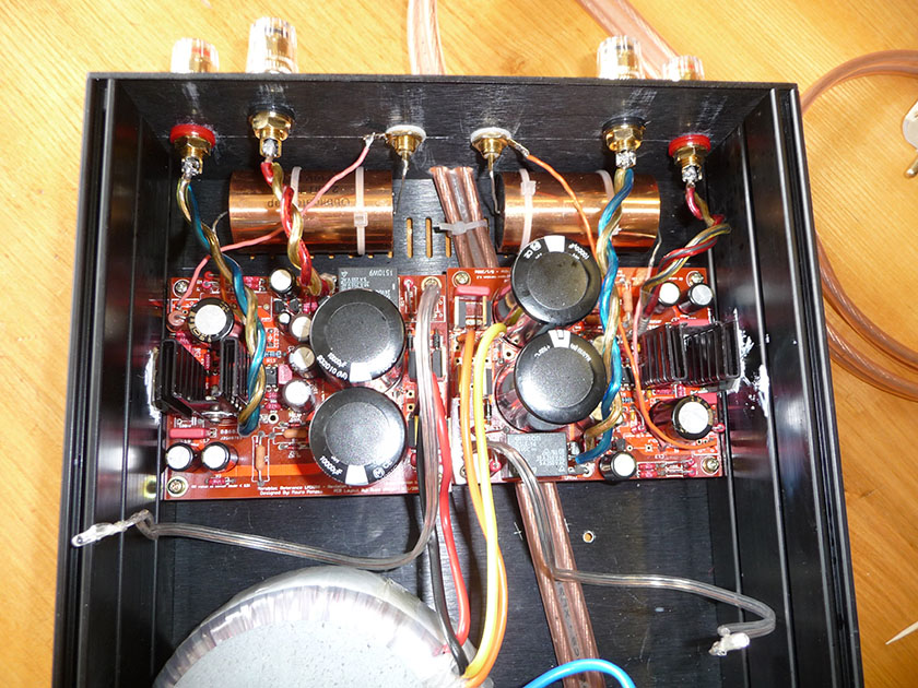
My comment was he should NOT being using speaker cord for mains power. See the speaker wire exiting the rear panel at the lower, center spot...
diyAudio
I suggested a "standard" power entry connector such as the Neutrik power-con or the common IEC socket.
If he chooses not to use a chassis connector for power then he can use the "old standard" of captured cord where a "fixed" power cord (cord meaning multiply conductor not single wire) is permanently attached to the chassis with a grommet / fastener.
Similar to this type:
untitled
ApexJr Subwoofer Amps
At no point did I ever comment on the ground or noise issue. I only addressed the speaker cable as mains cord safety issue. And I am really hoping he has at least a mains fuse in the chassis.
EDIT: Dude it was REALLY painful trying to find a picture of the "old style" fixed power cord entry.. I think everything has moved to detachable power cords.. Even TV's and cheap DVD players....
Last edited:
Ah, ok I see now what you meant. When you said to take a cord to chassis I thought you meant as some sort of grounding.
My comment was he should NOT being using speaker cord for mains power. See the speaker wire exiting the rear panel at the lower, center spot...
I do agree completely.
Speaker cable isn't safe for mains voltage...
The best thing is to mount an IEC inlet, and connect PGND to safety ground, even if it's disconnected... IMHO
When Vlad will have a safety ground his amp will be ready. 😉
few steps to improve my amp
Thanks for the power-discussion. When listening to several experienced builders the the transparency enters my brain. nice medicine.
It's clear for me that I should add some hardware, so please recommend the brand or DIY source for:
- good mains cable
- mains fuse (I thought it is superfluous accessory decreasing the sound quality)
Also what solution could helps to eliminate the hum/noise and woofer bang when switch on?
I think when I have safety earth in my flat I'll connect PGND to it, but I can't do it right now. and I want to listen to my new amp.
If I connect the on-board PGND to the case right now without earthing - is it good or bad idea?
Vlad
Last edited:
this is equivalent to building a double insulated amplifier without the double insulation and without the testing to prove it is safe to connect to the mains.......If I connect the on-board PGND to the case right now without earthing - is it good or bad idea?
I cannot advise that a power amplifier be connected to a mains wiring system that does not have Protective Earth as the third wire.
power connections
I'm thinking to organize my system' (cdp, pre, poweramp) power connections with Neutrick powerCONs (thanks troy).
1st way: I'll add powercons to all my devices and connect the power in chain, i.e input power from the wall socket firstly goes to cdp' powercon-IN, then from its powercon-OUT to pre, and finally from pre to poweramp.
2nd way: I'll build the splitter with powercon-OUTs which will be connected to inwall socket. All devices (supplied with powercon-INs) will be powered from the splitter with separate wires.
Please advise
- which way is better ?
- does powercon-based system sound worse then IEC ?
Vlad
Last edited:
Thermal Pad
Is an aluminum oxide thermal pad superior to mica? They're only 50 cents each and I have a Mouser order going anyway.
4170G Aavid Thermalloy Heatsinks
TIA,
rick
Is an aluminum oxide thermal pad superior to mica? They're only 50 cents each and I have a Mouser order going anyway.
4170G Aavid Thermalloy Heatsinks
TIA,
rick
possibly, it depends on the relative thicknesses and flatness of the two types of insulator.
1thou/mil or 0.001inch/0.025mm is hard to match never mind improve on.
Both types need thermal compound at both interfaces to eliminate air from the thermal path.
1thou/mil or 0.001inch/0.025mm is hard to match never mind improve on.
Both types need thermal compound at both interfaces to eliminate air from the thermal path.
LM318 socket
Is it correct that there is no directionality to the LM318 socket? Half of mine face one way and the other are opposite. As long as I correctly insert the IC in the appropriate orientation, then all is well? I was reading on another project and the author stated to be sure and get the socket in the correct orientation and now I need to verify before applying power.
TIA,
rick
Is it correct that there is no directionality to the LM318 socket?
Not sure if I understand the question correctly, but it sure is directional. Pin 1 is right below the notch on the socket, and Pin 1 on the IC (marked by a dot) has to go into Pin 1 of the socket - it can't go into Pin 5.
The silkscreen also shows which way the notch in the socket has to face when the socket is inserted.
The sockets have an orientation marker but it is purely cosmetic. If the socket was soldered in backwards but the opamp is installed in the correct orientation it will work. However if the opamp is removed there is a high probability of the replacement being installed incorrectly.
- Status
- Not open for further replies.
- Home
- Amplifiers
- Chip Amps
- MyRefC build guide