I had succesfully soldered my terminals. I had no problems with them, solder sticked nicely. Not as nice as with other components, but no more than 320º were needed. Really, mine soldered fine.
I am using kester solder 66/44. I didn't use flux.
I am using kester solder 66/44. I didn't use flux.
Don't use the terminals. Solder wires directly to the board, especially the outputs. Think about how often you will want to disconnect/reconnect anything. Problem mostly or completely solved, and better sound.
Peace,
Tom E
Peace,
Tom E
I basically added the terminals because I didnt want half of the people to complain that they werent there. I would usually prefer a soldered connection as well. If you will remove the amp a few times, if you tinker, you might leave them in.
I had no problem soldering mine. I first put a small screwdriver in the terminal and opened it up a little. Then put the wire in and crimped it and soldered. Soldering wasnt a problem. Dont think I used flux, but used a rosin core solder. Flux would have helped. If you dont open up the end a little you might have solder wick into the spade part of the terminal which could be a problem when you try to plug it into the board.
Uriah
I'm only using the terminals for the power input, not for the speaker output. The cable end is no problem, I've got good crimping tools.
I've finally managed to solder the terminals to the board. Found some old 60/40 solder, worked perfect without extra flux or sanding/scraping of the terminals. Seems the coating on the terminals didn't like the 2% of copper in my other solder.
I've finally managed to solder the terminals to the board. Found some old 60/40 solder, worked perfect without extra flux or sanding/scraping of the terminals. Seems the coating on the terminals didn't like the 2% of copper in my other solder.
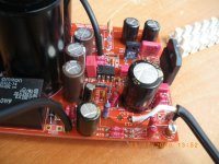
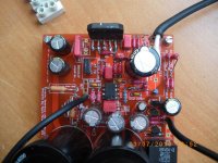
I have done that with the output and the ground to the speaker, but for connecting the trafo I have soldered three terminals. Not that I am using them, but they are soldered. There are holes enought for soldering the cable and APART from that, soldering the terminals too. They can be used to hook up test probes.Don't use the terminals. Solder wires directly to the board, especially the outputs. Think about how often you will want to disconnect/reconnect anything. Problem mostly or completely solved, and better sound.
Peace,
Tom E
In fact, the kit comes with 3 terminals, so not enought for the 5 connections.
For the cable terminals (female), I like to crimp and then solder, like Uriah does.
Hi Guys,
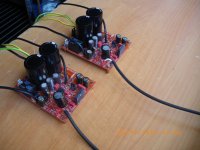
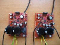
I finally had the time to compare the latest MyRefC ultimate BOM amp with a MyRefC classic from Twisted Pear that I built several years ago.
The differences :
The classic has only one 330 VA traffo and is DC coupled to a Twisted Pear Kookaburra preamp in a single case integrated amp build.
The Ultimate BOM is built dual mono with two 25 vac trafo from Apex Jr. Hooked up to a SKA dual mono preamp.
Keep in mind that the preamps may have affected the results, but this is what I heard.
The UB was clean and clear, but bass shy at first, I ran it for about 12 hours and bass response came back to the classic levels, then I did the comparison.
Tonality between units is very very close, base response is very close, but maybe tighter/better on UB. The UB had noticably lower noise floor, I had thought that the classic was very silent, before I compared it to the UB. Low level detail more easy to pick out with the UB. UB smoother and more liquid than the classic. The classic seemed a little grainer, for want of a better word. The classic sometimes had a hard edge with some kinds of music like piano, that was gone with the UB. Dynamics seemed about the same, but the imaging was clearly better with the UB. Soundstage about the same size but UB deeper, probably due to the lower noise floor, with live recordings the illusion that you are there was stronger. The differences were clearly audible.
All in all the classic integrated that I built is a great amp, but the UB has certainly improved this great design.
PJN
(Glad to see you caught the channel indicator issue)
I searched for this with no joy. Could you elaborate, please?

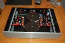
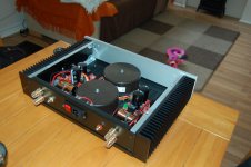
In your second picture you had the right and left RCA insulators backwards. Looking at the back side of the amp the right channel should be on the left side so the speaker leads would not have to cross at the back of the amp.
But in other pictures (1st, 3rd and 4th) the insulators were correct so I "assumed" you caught that and corrected it.
But don't let that distract from the first comment. Beautiful execution. VERY well done.
But in other pictures (1st, 3rd and 4th) the insulators were correct so I "assumed" you caught that and corrected it.
But don't let that distract from the first comment. Beautiful execution. VERY well done.
Last edited:
Thank you. In electronics attention to detail is everything as you have demonstrated beautifully here..
Shark, it totally reassembles mine! I've been "enclosuring" it these last days with a very similar case from the same manufacturer, so it has the same interior and boards.
I'll post in a few days.
Regards,
Regi
I'll post in a few days.
Regards,
Regi
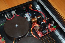
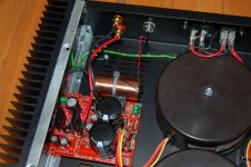
Regarding another matter, I have placed the tantalum resistors. I was able o put in the 3k3 input ones not without difficulties. They lead pitch is bigger than the holes in the board, so I wasn't able to try the 390r.
You can see how I managed to place the 3k3 resistor. Using one of the bigger holes of the input cap and a bit of the older resistor's lead.
I will post listening results as soon as I hook it up
You can see how I managed to place the 3k3 resistor. Using one of the bigger holes of the input cap and a bit of the older resistor's lead.
I will post listening results as soon as I hook it up
Attachments
Who makes those cases, and do the heatsinks come with them?
HiFi 2000 in Italy, the model is Pesante Dissipante
- Status
- Not open for further replies.
- Home
- Amplifiers
- Chip Amps
- MyRefC build guide