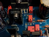
I soldered all the smd parts,
about R37 is it correct the one with 332 marked? Because I found in mouser bom also the 3301.
Thank you
Matteo
about R37 is it correct the one with 332 marked? Because I found in mouser bom also the 3301.
Thank you
Matteo
An externally hosted image should be here but it was not working when we last tested it.
An externally hosted image should be here but it was not working when we last tested it.
Hi,
my age prevents me from trusting myself...
I'm afraid I was wrong about the orientation of film caps.
In his tutorial Dario explains that Wimas orientation can be identified by a small sign.
In the attached picture I've made a black little dot in correspondance with these signs.
Can you help me to understand if I have respected the right orientation?
In case I want to try the Amtrans, can you post a picture of their correct orientation?
The images and captions published in the excellent tutorial of Dario are not entirely clear to me (yes, my age! ...)
Thank you for help
Ciao!
Giacinto
Attachments

Dario will sauté me in olive oil and top with fresh basil for saying this, but the polarity or orientation of film caps is live the polarity of wire or resistors.
If you believe it makes a difference it does. If you do not believe in this it is not audible. I do not know, but orient all mine the same way with respect to signal flow. But never have changed them all to see if it is right or wrong.
There is a little science here. Some feel the outer layer needs to be connected to the source. Others say the outer goes to the load. This is spiral wrapped caps.
I use a lot of stacked film caps and orient the printing to read with signal flow. But they look identical in construction.
With one transformer you will have more crosstalk between channels, with two you will have less.
Thanks mate, I will stick to two transformers than probably. The other amp I am building will be a 1 transformer amp and as yours should be the superior one anyway, i'll try to max it out. 🙂
One question I have been wrestling with is using an input transformer. I used to use a line stage with Cinemag input transformers for dc blocking and to allow easy single ended to balanced conversion.
I considered using them with a My_Ref in the past. The coupling cap (C13)always made me think this was not a good option.
My current dac has TRS outputs and I am using TS plugs to get single ended output for my Evolution. Thinking of omitting C13 and using an input transformer when building the Fremen.
Does anyone see an issue besides loss of fidelity from this? The power transformers are in separate enclosures so hum pickup should not be an issue.
I use a subwoofer and high pass at 65 Hz to this amp. So low end phase shift and roll off are minimized in my setup. My dac is four channel, use a 64 bit software crossover.
One question I have been wrestling with is using an input transformer. I used to use a line stage with Cinemag input transformers for dc blocking and to allow easy single ended to balanced conversion. ......
Thinking of omitting C13 and using an input transformer when building the Fremen.
Does anyone see an issue besides loss of fidelity from this? The power transformers are in separate enclosures so hum pickup should not be an issue.
I use a subwoofer and high pass at 65 Hz to this amp. So low end phase shift and roll off are minimized in my setup. My dac is four channel, use a 64 bit software crossover.
I have some limited experience with input transformers on a different amp project. In fact, I was working with Cinemag 1:1 transformers. There is a lot to pay close attention to with input transformers. For example, they are sensitive to the impedance of the circuit downstream from them. If I remember correctly, low impedance is better for damping/ringing but higher impedance is better for bandwidth up to a point. There may also be differences in down stream noise depending on impedance. For example, the transformers I was using wanted 10k input impedance for the amp, with 12k being possible. The FE has 100k input impedance and I don't know what would happen if you dropped it to 10k. Certainly, other interactions would be possible.
Whatever you do, the input transformer will likely significantly reduce the bandwidth of the amplifier and that may change the sound character of the resulting amp.
I guess I'm not trying to dissuade you from trying input transformers. They do nice things for input noise isolation. But be aware that there are lots of potential side effects.
Jac
Thanks, I still want to see. May play withR13 to load the transformer more efficiently. The 100K set the high pass through C13. Without a cap it can be a lower value.
Thanks, I still want to see. May play withR13 to load the transformer more efficiently. The 100K set the high pass through C13. Without a cap it can be a lower value.
Definitely go for it. Trying stuff is a big part of this hobby.
Okay, so I powered up one of my boards with a variac and heard the relay click. Then I checked the voltages at the test points printed on the boards and they were all within a few hundredths of the printed value.
When I connected a source and a test speaker, all I got was a squeal. Where do I go from here?
When I connected a source and a test speaker, all I got was a squeal. Where do I go from here?
Where did you get your LM3886? I have another small amp that uses 3886, and when it failed (I don't know why, after quite a few years of service and nothing done to the amp or connections), it made some strange noises. Don't know what you mean by squeal, but that might be it.
Did you have any difficulty soldering the 3886, or did you stress any of the chip leads? Do any amp parts get hot? Assuming you have 2 monoblocks, does the other amp work?
Peace,
Tom E
Did you have any difficulty soldering the 3886, or did you stress any of the chip leads? Do any amp parts get hot? Assuming you have 2 monoblocks, does the other amp work?
Peace,
Tom E
Start with Dario's suggestion. Short the inputs and measure both DC and AC voltage.
Another thing to try. Ground the heatsink. George has found oscillation on some of his more adventurous builds and found that grounding the heatsink helps. Hopefully I told the correctly.
Jac
Another thing to try. Ground the heatsink. George has found oscillation on some of his more adventurous builds and found that grounding the heatsink helps. Hopefully I told the correctly.
Jac
Hi everyone. Years ago I made a stereo amplifier with the classic gainclone design and I was quite satisfied with it. for a number of reasons that ampli I had to give it, but in my warehouse I still have several lm3886t chips a nice dual toroidal transformer from 24volts 250VA and many quality components like capacitor resistors etc .. I would like to make an improved version of the classic gainclone and so I would be oriented to a Myres maybe an improved and updated. what do you recommend? I would like to find some pcb made for this purpose to buy. thanks to all of you for the help.
Get in contact with him: https://www.diyaudio.com/forums/members/clavefremen.html
He runs My_Ref FE group buys time to time, excellent lm3886 amplifier.
He runs My_Ref FE group buys time to time, excellent lm3886 amplifier.
Get in contact with him: https://www.diyaudio.com/forums/members/clavefremen.html
He runs My_Ref FE group buys time to time, excellent lm3886 amplifier.
Thanks a lot for the tips 😉
I was so excited my FE worked on first power up I started another thread. Offset ran about 4.5 mv on one channel and 2.5 mv on the other after a couple hours. No playing just warming up.
Did a little heat sink work the next day and I had 800 mv on one channel. Was concerned the LM3886T was damaged when it was tightened back up after reinstalling a heat spreader.
But flipped over to check voltages and saw the offset changed channels. Found a loose connection on the output of the power transformer. Tightened up and offset is back to original value.
Not sure I like the dual diode bridges used. A single bridge definitely can work fine. Maybe not with a pseudo symmetrical voltage regulator circuit. But both can be worked around.
Hope get some music playing tomorrow. Wanted it to run for a while before hooking to the speakers. It has about five hours now.
The protection circuit did not trip when there was 800 mv of offset. I would not want to run that much dc through the woofers long term.
Put several hours of playing the FE this weekend. It was a little opaque at first. Resolution seemed lacking.
Got up close and heard some hum from the midrange and some diode hash from the tweeters. These are 106 dB efficient horns, a few mV is audible.
Grounded the housing on the input connectors and the amp is now silent. The connectors are Amphenol Twinax BNC. Two pins, the balanced input was floating.
The sound is very clean. Seems it can flesh out a little. Need to play it for a few weeks to let the capacitors form. It has 12 hours or so total powered up and maybe three playing at mW level.
Great job Dario!
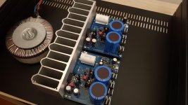
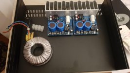
Power supply and layout
Hi everyone. I am waiting for the arrival of the two cerafine capacitors to be able to start testing the amplifier. I have two doubts one on the power supply, I have a dual 24v 250VA transformer according to you I can use it? and then better the layout with the transformer behind the sink in order to use it as an interference screen or the second layout? Thank you all for the answers.
Hi everyone. I am waiting for the arrival of the two cerafine capacitors to be able to start testing the amplifier. I have two doubts one on the power supply, I have a dual 24v 250VA transformer according to you I can use it? and then better the layout with the transformer behind the sink in order to use it as an interference screen or the second layout? Thank you all for the answers.
Attachments
- Home
- Amplifiers
- Chip Amps
- My_Ref Fremen Edition - Build thread and tutorial