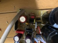
Check the 1 ohm resistor (R11 if I remembre correctly)
How about adding 2 diodes, back to back, on the next board revision to prevent this from happening.
Check the 1 ohm resistor (R11 if I remembre correctly)
Yes, it seems that R11 is broken. In the afternoon I will desolder it and check better.
So I have to replace lm3886, R11 and lm318?
is there a way to understand if lm318 or lm3886 are still good?
My fear is about lm318 because it is smd and I never solder smd...
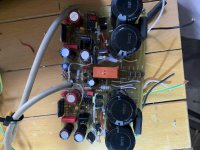
the first My_ref amplifier alive and well ,with almost all evolutions and your modifications in fifteen years!
Great sound with shunt power supply , but not so easy to upgrade in this old board
A way to keep your mind busy in this unhappy moment.
Great sound with shunt power supply , but not so easy to upgrade in this old board
A way to keep your mind busy in this unhappy moment.
Attachments
Fixed
In a previous post I reported the sound signature what not at all as expected. Today I'm breaking in the speakers and indeed the bass starts to become more present. But still nothing close to what I was expecting.
Started going over the build guide again and found my mistake: I soldered C10, but not R39 .
.
Removed C10 and there it is! The My_Ref Fremen the way it is supposed to sound. I can reconize all my songs again 🙂.
For learning purposes: can someone explain why C10 without R39 has this impact?
In a previous post I reported the sound signature what not at all as expected. Today I'm breaking in the speakers and indeed the bass starts to become more present. But still nothing close to what I was expecting.
Started going over the build guide again and found my mistake: I soldered C10, but not R39
. Removed C10 and there it is! The My_Ref Fremen the way it is supposed to sound. I can reconize all my songs again 🙂.
For learning purposes: can someone explain why C10 without R39 has this impact?
Last edited:
These components are integral to the feedback loops. The 470K is the third order filter. I would not have expected C10 removal to flatten the low end response.
I may have misread, try the circuit with R39 and C10 installed.
I may have misread, try the circuit with R39 and C10 installed.
Started going over the build guide again and found my mistake: I soldered C10, but not R39
Removed C10 and there it is! The My_Ref Fremen the way it is supposed to sound. I can reconize all my songs again 🙂.
For learning purposes: can someone explain why C10 without R39 has this impact?
Which compensation scheme are you using? FE or Evo A? 😕
No C10 and no R39 points to Evo A but then R3 MUST be 0.33R, which value do you have there?
BTW, yes omitting or changing compensation parts could have a BIG impact on sound (and STABILITY).
I'm using Evo A, now. My mistake was that I wanted to use Evo A, but soldered C10 (not properly reading while doing some late night soldering).
I can confirm R3 is 0.33R.
And I can also confirm it sounds great now!
I can confirm R3 is 0.33R.
And I can also confirm it sounds great now!
Last edited:
No, just replace R11. It connects the input ground to the power/output ground.
So guys...
It seems that I'm very lucky man and the schematic is well done

Replacing R11 with equivalent res and with fly connection, everithing works fine and I'm able to hear the music

Now I have to order the right res...
I hope that next week I can post my impressions on both channels run 😀
Thanks
Nice! Nice job with the regulator!
I loved for so long, mine RefC original..
Ciao, George (still have it..)
I loved for so long, mine RefC original..
Ciao, George (still have it..)
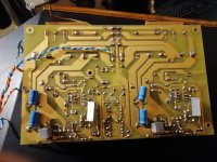
the first My_ref amplifier alive and well ,with almost all evolutions and your modifications in fifteen years!
Great sound with shunt power supply , but not so easy to upgrade in this old board
A way to keep your mind busy in this unhappy moment.
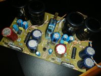
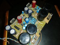
Pardon for trolling but here it is.
2006....
Ps: George might realize some 'features' - - and Mauro is rolling in his rest..
2006....
Ps: George might realize some 'features' - - and Mauro is rolling in his rest..
Attachments
Last edited:
Pardon for trolling but here it is.
2006....
Ps: George might realize some 'features' - - and Mauro is rolling in his rest..
Those pictures would have gotten you placed in Mauro’s blocked senders list.
Yess...
Though. I have kindly, but insistently fought back about the diode bridge.. And he started to think..
But the bright one, it was him, I was just putting forward a different experience.
About the rest, I kept silent and went my way.. 🙂
Ciao, G
Though. I have kindly, but insistently fought back about the diode bridge.. And he started to think..
But the bright one, it was him, I was just putting forward a different experience.
About the rest, I kept silent and went my way.. 🙂
Ciao, G
By the way, in the photo R3 is an ATE 5CS wirewound resistor. It's the Ayrton Perry wound variant, but I have to say that later I changed to the standard ones simply.
I find these very nice, still today. Even against / beside the Isabellenhutte PBH ones.
Did You get them?
G
I find these very nice, still today. Even against / beside the Isabellenhutte PBH ones.
Did You get them?
G
Not smart enough bough to my rder
I have tried using Google to place an order. I am not getting it. These translation codecs are vague on items. Have not gotten an account yet for the same reason.
By the way, in the photo R3 is an ATE 5CS wirewound resistor. It's the Ayrton Perry wound variant, but I have to say that later I changed to the standard ones simply.
I find these very nice, still today. Even against / beside the Isabellenhutte PBH ones.
Did You get them?
G
I have tried using Google to place an order. I am not getting it. These translation codecs are vague on items. Have not gotten an account yet for the same reason.
I have often used these resistors in speaker crossovers. Ate CS is a normal wound resistance. If you want the Ayrton Perry anti inductive winding you have to order the CSN type (the suffix N is the key) and generally they must be ordered at the factory. In Italy the Ate SCSN are on sale from Audiokit, I don't know if they ship in the USA. A 0R33 costs € 4.67 plus shipping.
Ciao a tutti
Giacinto
Ciao a tutti
Giacinto
Probably this can be a very stupid question...
For the input signal I buyed a balanced cable van damme 268-006-000.
Which is the best way to connect to CMC-805-2.5-F?
I found on google that I have to solder together the cold pin with the shield. Is this the correct way or I have to leave the shield unconnected?
For the input signal I buyed a balanced cable van damme 268-006-000.
Which is the best way to connect to CMC-805-2.5-F?
I found on google that I have to solder together the cold pin with the shield. Is this the correct way or I have to leave the shield unconnected?
so...
on the RCA side:
- positive wire in the center of connector
- negative wire and shield, together, on the external part of the connector
on the PCB side
- positive wire to positive pin
- negatice wire to negative pin
Is this correct?
on the RCA side:
- positive wire in the center of connector
- negative wire and shield, together, on the external part of the connector
on the PCB side
- positive wire to positive pin
- negatice wire to negative pin
Is this correct?
C10 on ver 1.05 boards
Dario: I’ve acquired a set of Ver 1.05 PCBs from someone and want to build a basic EVO A version. The BOM for "up to 1.2" has C10 occupied with a 33pF CDE cap. Is this correct? The BOM for my Ver 1.7 PCBs had C10 unpopulated for the EVO A build.
Also, will your new PCB version have the ability to mount TO247s at R3?
Many thanks,
Pete
- Home
- Amplifiers
- Chip Amps
- My_Ref Fremen Edition - Build thread and tutorial