IMHO soldering is the problem.... let us know how it evolves.
With RC boards one of the partecipants had similar problems with one channel, he sent it to me and I redone all SMD soldering, problem solved (I can't remember now if LM318 was changed too)
Hello Voxxonline,
I may be wrong but I see Q1 transistor in wrong position in your pic (post #293). This could be a reason why there is no click on output relay.
Regards,
I may be wrong but I see Q1 transistor in wrong position in your pic (post #293). This could be a reason why there is no click on output relay.
Regards,
My_ref_FE built and working
Hello,
this is just to thank Dario and all the people involved in the development of the board of such a wonderful ampli 🙂.
Yesterday I've mounted my boards (first group buy) with the mouser bom and both worked impeccably.
Some info:
- before mounting each component, it could be obvious, I checked it (measuring the resistance, checking diodes, reading types on transistors, etc) and, lucky me, I found no error at all from Mouser.
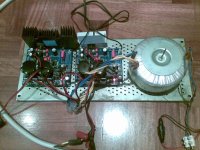
- I'm using one trafo (22V+22V, 350VA) from LSP transformers (Italy). My speakers are 4Ohm nominal (AR 312HO),
- the picture shows the boards and the trafo of the first "run". I'll put everything in the galaxy GX288 enclosure very soon.
Hello,
this is just to thank Dario and all the people involved in the development of the board of such a wonderful ampli 🙂.
Yesterday I've mounted my boards (first group buy) with the mouser bom and both worked impeccably.
Some info:
- before mounting each component, it could be obvious, I checked it (measuring the resistance, checking diodes, reading types on transistors, etc) and, lucky me, I found no error at all from Mouser.
- I'm using one trafo (22V+22V, 350VA) from LSP transformers (Italy). My speakers are 4Ohm nominal (AR 312HO),
- the picture shows the boards and the trafo of the first "run". I'll put everything in the galaxy GX288 enclosure very soon.
Attachments
It looks like the schematic link is down.
I just had a thud come through when powering up this morning.
Does anyone no how to increase the turn on delay time for the relays?
I just had a thud come through when powering up this morning.
Does anyone no how to increase the turn on delay time for the relays?
It looks like the schematic link is down.
https://docs.google.com/file/d/0B-qKRBuaKtzYTG15RklBS1RkdUU/edit?usp=sharing
In which thread /post the schematic link is broken?
Tell me and I'm gonna fix it
I just had a thud come through when powering up this morning.
Does anyone no how to increase the turn on delay time for the relays?
Mmh, strange, the thud should not be heard, never felt the need to increase the dealy time...
my mistake the google link is fine, I just needed to log in so google can track everything i do.
What component adjusts the delay time?
Id rather be safe than sorry.
What component adjusts the delay time?
Id rather be safe than sorry.
Thermals
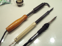
The construction went on in a troublesome manner until it was time to solder the thermals. 70 W Goot PX-251AS soldering station definately failed to heat thermals. I have been using this station for a few years. Mostly for digital PCBs with small pads and thin tracks. But even then I suspected that the temperature of the tip was not up to the numbers on control dial. With the thermals, at 400C it was like mixing butter with a spoon. Most problematic thermals were R104, R201, C1, C2, C9, central contact of relay. And the tutorial warns that the major trouble is still ahead with C101, C201! So, one way out was to use ancient irons. The ones in the picture are 90W, 65W (both with 10 mm wide flat copper tips) and the Goot product for comparison. The 65 W was enouh to do the job. It turned to be more efficient, then the 70W ceramic type... Now, I certainly can not recomend anyone to use these type of irons, mainly because they are considered not safe to use with semiconductors. Soon we'll see if I got away with it, or not... In future I will be searching for another solidering station.
The construction went on in a troublesome manner until it was time to solder the thermals. 70 W Goot PX-251AS soldering station definately failed to heat thermals. I have been using this station for a few years. Mostly for digital PCBs with small pads and thin tracks. But even then I suspected that the temperature of the tip was not up to the numbers on control dial. With the thermals, at 400C it was like mixing butter with a spoon. Most problematic thermals were R104, R201, C1, C2, C9, central contact of relay. And the tutorial warns that the major trouble is still ahead with C101, C201! So, one way out was to use ancient irons. The ones in the picture are 90W, 65W (both with 10 mm wide flat copper tips) and the Goot product for comparison. The 65 W was enouh to do the job. It turned to be more efficient, then the 70W ceramic type... Now, I certainly can not recomend anyone to use these type of irons, mainly because they are considered not safe to use with semiconductors. Soon we'll see if I got away with it, or not... In future I will be searching for another solidering station.
Attachments
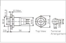
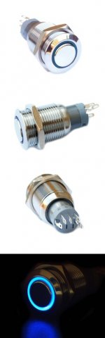
Gents, can you explain please how to connect switch to transformers?
It has NC (normally closed) NO (no voltage) and C - common.
It has NC (normally closed) NO (no voltage) and C - common.
Ordered new q1 , thanx again spinwell[/QUOT
I can pop some in the post if you haven't already ordered.
Are you using a two pole switch i.e switching live and neutral?
Gents, can you explain please how to connect switch to transformers?
It has NC (normally closed) NO (no voltage) and C - common.
Hope this can help:
The switch was OFF at the moment of shooting
Attachments

I have one push button latching switch.
Sorry never wired any ac in my life so want to understand.
Basically one wire in, one out and voltage connects then button pressed.. Easy !
3rd wire is common- aka ground I guess.
Thank you 🙂
Sorry never wired any ac in my life so want to understand.
Basically one wire in, one out and voltage connects then button pressed.. Easy !
3rd wire is common- aka ground I guess.
Thank you 🙂
Common is usually the mains in with either of the others as out depending on the switch position.Do not connect ground to the switch under any circumstances.
OK. 🙂
Pardon my level of awareness .
Ok, I forgot it is OK to put switch after transformer. Or you prefer before ?
Pardon my level of awareness .
Ok, I forgot it is OK to put switch after transformer. Or you prefer before ?
- Home
- Amplifiers
- Chip Amps
- My_Ref Fremen Edition - Build thread and tutorial