Hi Bob,
Are you using this actual Jims Audio ebay JC-2 kit with the FE amp and if so, have you modified it in any way?
Also, I think the FE amp is rated at 45W - my speakers are not that efficient/sensitive at around 85 dB. Any opinions if the amp shines on more sensitive speakers closer to 88-90 dB?
Thanks
While we are waiting for the boards, I would like to suggest an outstanding unit to push the Fremen Edition amps.
Many builders will find simple attenuation like a bare pot or an LDR device to be an excellent approach. For situations that require some gain, I would like to suggest the Jim’s Audio JC-2 kit. It is referenced to the JC-2 designed by John Curl and others and is described as a “straight wire with gain” solution.
I have started a new thread around this package with the intent of getting as many eyes and brains focused on possible component upgrades and optimization.
The preamp sounds fantastic as shipped from the supplier, but a process similar to the ongoing Mini 2948 DAC conversations could possibly lead to even better performance. Please take a look.
http://www.diyaudio.com/forums/analog-line-level/214380-ja-pre-myref-fe-integration.html#post3057400
Last edited:
Jc-2 is not the real JC-2
Have a look here on the post #4 http://www.diyaudio.com/forums/solid-state/120243-variation-jc-2-preamplifier.html what is saing Mr. Curl about this kit sold by Jims Audio so called Jc-2.
Have a look here on the post #4 http://www.diyaudio.com/forums/solid-state/120243-variation-jc-2-preamplifier.html what is saing Mr. Curl about this kit sold by Jims Audio so called Jc-2.
OOPs.The DC detect does not seem to detect -ve output offset. I shall investigate further.
I just did not turn up the DC offset test signal high enough.
It triggers at ~-6Vdc to -8Vdc depending on how fast/slowly one winds up the offset.
The Input RCA ground ground is part of the Audio signal processing circuit. It MUST be connected to the Main Audio Ground (MAG). You have no choice in that..............If the RCA ground is connected to the chassis, it would also be connected to safety ground, wouldn't it? Think I did something like that initially, and got hum. But I may have connected differently, will give it a try again.
For Safety reasons alone, the MAG must be connected to chassis, again no choice. That is a quite different issue/connection from the RCA ground connection.
What currents pass through this bridge loaded Zener? The Currents are certainly not Zero when the [Vout - V-IN] < 27Vpk...............Because of the low supply the clipping Zener protection did not kick in early enough,................... a lower Zener voltage to check what the clipping protection effectively does ..................use a different Zener (D3) than the stock 27V.
Does that current flow affect the signal passing through the amplifier?
I'm so glad to see that some Members are awake !Stability is one of the things that has been neglected in this project in my view. .......................all the reports of the smallest change in components or their placement causing major changes in the sound makes me wonder - is it really stable?
Why don't you try what you say on the MyRef and see what happens to your speakers.😀The Input RCA ground ground is part of the Audio signal processing circuit. It MUST be connected to the Main Audio Ground (MAG). You have no choice in that.
For Safety reasons alone, the MAG must be connected to chassis, again no choice. That is a quite different issue/connection from the RCA ground connection.
Is your question asking, because you think what I have posted is wrong?
Or, do you think that I don't do as I say?
If it's something else then I don't understand your question.
Or, do you think that I don't do as I say?
If it's something else then I don't understand your question.
marcus1,
Yes, that is the kit I have. I got some component upgrade suggestions from both Stanton Tin (the supplier) and Dario several months ago but have not changed anything yet.
I purposely used only the bare pot for all the swapping and testing throughout the beta build. I suspect that could be all that's needed for more efficient speakers. Again, we are dealing with personal preferences in what volume levels appear as "live" or realistic SPL. I lean toward what others might consider loud.
You can get some insight into the quality of the sound produced from the following:
I have both the Lighter Note and the Lightspeed LDR units from Uriah. They are supper clean and remarkably similar to a bare pot. Uriah got the opportunity to audition the official Parasound JC-2 ($4000.00) and could not hear any difference between it and the LDR products. He was a little dissapointed, but to me that indicates both designs are approaching the straight wire with no coloration goal.
Stanton has reported that several of his customers have replaced pres from Goldmund with his kit.
With approval, I will post the suggestions form Stanton and Dario on the other thread.
atupi,
That post and others are the reason I contacted Parasound directly yesterday. There is obviously some tension there between the designers and the company, but John has been very active in the DIY community none the less. I've sent him several messages but haven't received any replies to date. The responses I got from Parasound were from Richard Schram, Company President, and his only concern was that it be clearly noted that the DIY efforts do not get confused with what Parasound has done. He was gracious and expressed no attempts/thoughts to dissuade experimenters as long as the distinctions were made. I also sent a copy of that conversation to Stanton with the suggestion he make the proper changes to his eBay post/description.
I'm glad there has been some response to this idea and we can continue over on the other thread,
Last edited:
Is your question asking, because you think what I have posted is wrong?
Or, do you think that I don't do as I say?
If it's something else then I don't understand your question.
Connect the MAG the way you said on the MyRef and see what happens.😀
Elna Package
- SoIL4x4
- lehmanhill (x2)
- b.veneri
- badrisuper
- SoIL4x4
- lehmanhill (x2)
- beneri
- badrisuper
My MyRefC is connected as post924.
RCA input connected to MAG via the 1r0 on PCB.
What do you see as the problem?
At the moment and probably for quite a few weeks/months the MyRefC will not be inside a chassis and so the PE will not be connected to MAG. It will when I fit it inside a chassis.
RCA input connected to MAG via the 1r0 on PCB.
What do you see as the problem?
At the moment and probably for quite a few weeks/months the MyRefC will not be inside a chassis and so the PE will not be connected to MAG. It will when I fit it inside a chassis.
Monoblocks
"The FEs must be used as monoblocks with dedicated transformer for each already (Penasa's suggestion for the double bridge approach)."
I guess I had missed this information. Can anyone point me to further information on why this should be? I don't understand why two My_Ref or FE boards with their own rectifiers and smoothing caps shouldn't be connected to one transformer as long as the transformer out connections were in parallel.
Hmmnn. Something else for me to learn and understand.
Jac
I too would like a little clarification. To me the term monoblock means a single channel with its own dedicated power supply in its own enclosure. Therefore you will need two enclosures for a stereo setup. Though I think what is being said here is that each channel needs its own power supply transformer, rectifier smoothing etc. Dual mono. That being said is there any reason that both channels can't or shouldn't be housed in one enclosure? I have read that there is still crosstalk between the channels, but should there be in a properly operating amp with only grounds meeting at a common point?
I am still going back and forth with idea of one stereo enclosure or two mono. I guess I will decide when the board and transformer are in front of me.
This is my approach for a single chassis. There are three toroids under the home brew square shield. These are Siva's V1.3 boards but the same design can be used with any MyRef.
http://www.diyaudio.com/forums/chip-amps/203666-myref-integrated-solutions-11.html#post2902010
http://www.diyaudio.com/forums/chip-amps/203666-myref-integrated-solutions-11.html#post2902010
Updated BOM
I have just uploaded on the Google Folder an updated BOM.
In the previous one there was an error (1 LM317 instead of 2).
I've added, as a second sheet in the same file, a 'On a budget' BOM that costs about 52€ per monoblock instead of 76€.
The price reduction is possible replacing all Caddocks with lesser resistors and one of the Silver Micas (and some minor additional swaps).
BOM should be ready for ordering but some minor errors are still possible.
I remember to all partecipants that the BOM is for one (1) monoblock, so quantities should be doubled for a complete stereo set.
There's no need for two enclosures but two transformers are required.
It will probably works as well with a single transformer (not tried, thought), Penasa was worried that the two double bridge boards with a single transformer could have problems with the virtual ground/hum.
I don't have have the knowledge to confirm or not so I've decided to simply follow his suggestion.
I have just uploaded on the Google Folder an updated BOM.
In the previous one there was an error (1 LM317 instead of 2).
I've added, as a second sheet in the same file, a 'On a budget' BOM that costs about 52€ per monoblock instead of 76€.
The price reduction is possible replacing all Caddocks with lesser resistors and one of the Silver Micas (and some minor additional swaps).
BOM should be ready for ordering but some minor errors are still possible.
I remember to all partecipants that the BOM is for one (1) monoblock, so quantities should be doubled for a complete stereo set.
I guess I had missed this information. Can anyone point me to further information on why this should be?
I too would like a little clarification.
(...) That being said is there any reason that both channels can't or shouldn't be housed in one enclosure?
There's no need for two enclosures but two transformers are required.
It will probably works as well with a single transformer (not tried, thought), Penasa was worried that the two double bridge boards with a single transformer could have problems with the virtual ground/hum.
I don't have have the knowledge to confirm or not so I've decided to simply follow his suggestion.
Last edited:
This way any HF on the cable shield will directly be diverted to the chassis and will not enter the circuit.Why you would connect RCAs ground to chassis (not safety earthed) and modules' input ground?
It started to get signficant over the electrostatic hum once I had one of the speaker wires close (<5cm) to any of the AC wires, running in parallel to it for a few cm. Once the AC lines are twisted together (each of the AC input pairs, that is), the emitting loop area is small so only little pickup will happen in the recieving loop. Keeping the receiving loop area small as well the effect will be reduced to insignificance (and that remainder will be dominated by the remaining loops on the PCB). Good wiring practice will totally avoid the issue, as a bottom line.how much close (speaker cables and secondaries) would induce a significant hum?
The dimensioning of the exact Zener value is affected by the following:The limiter, as I've later discovered, is identical to Penasa's My_Evo one.
The only goal is to avoid a destructive behaviour.
Since the LM318 is supplied with 14V rails shouldn't be the limiter fixed at 28V? 😕
a) the difference between rail voltage and Zener voltage. With unloaded amp, I found a safe difference of about 6V (33V rails and 27V Zener).
b) the amount of load current present. This will drop the rails a bit and will lower the margin. Further, a positive output current will make the LM318's output go negative and with a resistive load the output voltage will be positive, therefore the effective clamping level is reduced, the higher the current the more so. Since the dropout voltage of the LM3886 will also decrease with load current, this works in favor for us. With a purely reactive load the current will be zero when the output level peaks, so the clipping threshold will higher.
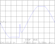
See following 'scope shots I made today, amp unloaded, 5kHz test frequency (for higher visibility). 10 Volts per division vertical scaling.
With slightly too low rail voltage (30V) :
The glitch on the recovery from negative clipping is very evidend. When going deeper into clipping, the glitch disappears and is replaced by severe rail sticking followed by a sharp transition back to the sine, sounding equally distorted as the glitch. With 4R load behaviour is very similar.
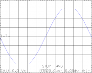
With 33V rail voltage :
Recovery is clean, only some small amount of rail sticking is seen on the negative recovery. Also, deeper clipping showed equally nice recovery.
The current through the Zener is limited by the LM318's short circuit current of 20mA. Because the Zener and the bridge are in parallel to C10+C32, any nonlinear capacitance will not have big effect. The bridge is effectively connected between two outputs.
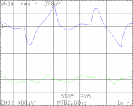
Finally, the ripple at the +14V line, with unloaded amp (bottom) and with 16 Watts (into 4R, 5kHz), 4700uF rail caps, reference against PGND :
(bandpass filtered from 10Hz to 300Hz to help the averaging, which also "killed" the 5kHz).
Unloaded, the ripple is a bit above 100uV peak, and loaded the peaks are 0.6mV. It is not perfectly clear wether it is dominated by the regulator ciruit itself or by I*R drops around the PGND node, but anyway is is quite low, the LM318 will be quite happy with that amount of ripple. Noise at the 14V lines will be dominating hum, it seems.
That'll be it for today.
Attachments
Last edited:
1 Tranny = 1 FE
Dario,
Thanks again for a polite and clear explanation of the why's and how's of your development of the FE. Now that I understand that Mauro's concern was with virtual ground/hum, I can pursue better understanding in this direction. Maybe a little experimentation, too.
All,
Since there continues to be further discussions/approaches to grounding, both safety earth and audio, I'll offer another approach I've seen in a high quality pre-amp. Jos Eijndhoven's Relaixed2 pre-amp uses an R22 resistor between the audio ground and the chassis/safety ground. That keeps it from building up voltage on the floating board. It also allows the pcb to float from safety ground and helps kill the hum. Although I've built the internals of the Relaixed2, like others, I am slower at building the chassis, so I can't confirm the concept. Jos has measured signal to noise at -123 dB, so the approach has measurements to back it up.
Do any of you with more experience than me (almost everyone) have any thoughts on the resistor to chassis ground idea?
Exactly, I'll clarify the reasons, but not today (err, tonight). It's late enough for me (1:30AM)...It will probably works as well with a single transformer (not tried, thought), Penasa was worried that the two double bridge boards with a single transformer could have problems with the virtual ground/hum.
This way any HF on the cable shield will directly be diverted to the chassis and will not enter the circuit.
Nice, but the Class II compliance is needed... I'm not sure to be able to do that...
It started to get signficant over the electrostatic hum once I had one of the speaker wires close (<5cm) to any of the AC wires, running in parallel to it for a few cm.
(...)
Good wiring practice will totally avoid the issue, as a bottom line.
I always twist AC wires so I never encountered this problem.😉
Now I know why, thanks! 🙂
Recovery is clean, only some small amount of rail sticking is seen on the negative recovery. Also, deeper clipping showed equally nice recovery.
So, if I've undestood correctly with 33VDC rails all seem to work as expected.
We could say that also with the 28VAC secondaries suggested for 4 Ohm loads the 27V zener is adequate?
Finally, the ripple at the +14V line, with unloaded amp (bottom) and with 16 Watts (into 4R, 5kHz), 4700uF rail caps, reference against PGND :
(...)
Unloaded, the ripple is a bit above 100uV peak, and loaded the peaks are 0.6mV. It is not perfectly clear wether it is dominated by the regulator ciruit itself or by I*R drops around the PGND node, but anyway is is quite low, the LM318 will be quite happy with that amount of ripple. Noise at the 14V lines will be dominating hum, it seems.
Seems good 🙂
You measured with C102/C202 in place?
Thanks again Klaus for your wonderful measuring job 🙂
- Status
- Not open for further replies.
- Home
- Amplifiers
- Chip Amps
- My_Ref Fremen Edition - Beta build/Fine tuning