To see how bad the hum is, you might consider using a PC and software like audio tester
audioTester
???
Klaus measured neglegible hum...
Put C9 with one end on the GND plane, the other end to R10. So, put R10 were C9 was and vice versa.What you mean exactly by 'exchange positions of R10 and C9'?
I can't see how...
Make the total copper area as small as possible by moving R10 and R7//C32 as close to the -IN pin as possible.Minimize trace lenght on -IN... you mean between -IN and C12 or the entire trace?
Yep, keep it, then we can use either a jumper or the resistor.Well, I imagine that it can be shorted with a piece of wire if needed but I would leave the position to be compliant with Mauro's design.
Well, length itself is not a problem, just keep loop area small. In fact moving R3 about 1..2mm to the left will do. Note that all this is inside of the feedback loop of the LM318 so any possible ill effects are not shining through directly.Doing this would lengthen the feedback loop, do you think it's mandatory?
I used the DC supply for that test of the relay circuit. We would need specify a minimum supply voltage, I'll check with real dual secondary transformer next. Fix could be to double C14 to 470uF and to halve R14 to 220R, that would halve the drop accross R14. The doubled ripple current will not be a problem, notably not with the new layout. What's the original spec for the xformer, resp. the rail voltage btw?How would you fix it?
Can't be due to the use of a single diode rectifier?
R21 could go to the +14V stabilized supply and would need to be decreased accordingly, another thing related to the relay circuit. Next, a second set of diodes adding to DR1/DR2 to the other AC input would be a stuffing option for those that want to use center tapped xformer.
R2 could go to the -14V (and decreased as well) to have more of a constant current behaviour for the mute pin current which is to be preferred.
I'll try these options and report.
As for the hum/buzz, it is there (faintly, but audible) with the ear-on-the-woofer test) even when powering everything with DC, but did not increase when powering the relay circuit from AC, so it is electrostatic pickup (heatsink was grounded, of course). Once you put it in a fully shielded box it will go away. Shorting the input is needed to exclude open input pickup, for true realism one could use some 100R or so (the typical output resistance from CD-player etc). The lab I work is very noisy electrically, when something is quiet there, it will be quiet mostly everywhere IME.
OK, enough for today, and note that this was all the result of a very quick testing session late in the evening.
What you mean exactly by 'exchange positions of R10 and C9'?
Connect R10 to the LM318 pin 3 with a very short trace. Then connect C9 to R10. The negative lead of C9 connects to C12 and R13 (input ground).
Doing this would lengthen the feedback loop, do you think it's mandatory?
Using a hex head screw allows a wrench to be used to tighten the screw. The wrench may have better access than a screwdriver.
How would you fix it?
Can't be due to the use of a single diode rectifier?
The MyRefC had two diodes in the relay circuit power supply. Did you change it? Reducing the value of R14 will raise the voltage to the relay. R14 should be chosen to work well with the transformer voltage in the amp.
I'm interested in more information about the Russian K71-4 caps. You mentioned that they are bigger than the space on the board. Can tell us the size (body diameter and length) and compare to the True Copper size? Bob's photo of the True Copper caps was instructive.
I ordered some K71-4 caps on Sunday, when they arrive I will measure and post the sizes. (If no-one beats me to it).
Bill
The price of the K71-4 caps is hard to beat, so I ordered a few today. For the price even if they are disappointing I wont be out much. Though I have read quite a few good reviews in other threads so I am looking forward to experimenting with these and a few other caps. Now we will see if the sellers estimated ship time to the US of 7-10 days will happen.
Bob mentioned earlier that these could be mounted directly to the rcas which I think is a great idea, its easy to solder and it keeps the paths short. I did that on my 4780 and it worked perfect, its makes removal easy too, you never have to worry about damaging the rcas as long as you mind the plastic insulators.
Bob mentioned earlier that these could be mounted directly to the rcas which I think is a great idea, its easy to solder and it keeps the paths short. I did that on my 4780 and it worked perfect, its makes removal easy too, you never have to worry about damaging the rcas as long as you mind the plastic insulators.
I ordered some K71-4 caps on Sunday, when they arrive I will measure and post the sizes. (If no-one beats me to it).
Bill
Whoa! Same time, same topic, different continent. Billo are you reading my mind😀
I ordered some K71-4 caps on Sunday, when they arrive I will measure and post the sizes. (If no-one beats me to it).
48 x 29 mm 😉
It's easy since I've them at home... 😀
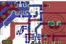
Put C9 with one end on the GND plane, the other end to R10. So, put R10 were C9 was and vice versa.
Make the total copper area as small as possible by moving R10 and R7//C32 as close to the -IN pin as possible.
Connect R10 to the LM318 pin 3 with a very short trace. Then connect C9 to R10. The negative lead of C9 connects to C12 and R13 (input ground).
This is a sort of a puzzle... but I'm pretty tired now 1.00AM here.
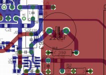
Maybe something like this?
Yep, keep it, then we can use either a jumper or the resistor.
Fine 🙂
Well, length itself is not a problem, just keep loop area small. In fact moving R3 about 1..2mm to the left will do. Note that all this is inside of the feedback loop of the LM318 so any possible ill effects are not shining through directly.
Something like this?
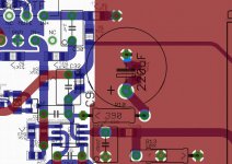
But in this way the output seems to me too near to the PS lines.
What's the original spec for the xformer, resp. the rail voltage btw?
2x25V (2x24V fine too)
Next, a second set of diodes adding to DR1/DR2 to the other AC input would be a stuffing option for those that want to use center tapped xformer.
I don't know...
R2 could go to the -14V (and decreased as well) to have more of a constant current behaviour for the mute pin current which is to be preferred.
How would you route 14V till the mute pin?
I'll try these options and report.
Interesting, thanks 🙂
As for the hum/buzz, it is there (faintly, but audible) with the ear-on-the-woofer test) even when powering everything with DC, but did not increase when powering the relay circuit from AC, so it is electrostatic pickup (heatsink was grounded, of course). Once you put it in a fully shielded box it will go away.
Fine to know, thanks 🙂
OK, enough for today, and note that this was all the result of a very quick testing session late in the evening.
Yes, enough for me too. See all tomorrow.
The MyRefC had two diodes in the relay circuit power supply. Did you change it?
No. Klaus used a single diode to maximize ripple in his measurements.
Attachments
Dario, if you are going to swap C9 and R10, I would STRONGLY recommend you listen to it on the beta board or old MyRef first.
This is a sort of a puzzle... but I'm pretty tired now 1.00AM here.
Maybe something like this?
I was thinking more like this:
Attachments
Dario, if you are going to swap C9 and R10, I would STRONGLY recommend you listen to it on the beta board or old MyRef first.
I was thinking more like this:
Thanks, more clear. 🙂
Now I understand why I couldn't imagine that... you were suggesting to swap C9 and R10 in circuit, not in layout...Klaus, do you meant the same thing?
I think this thing has to be tested and it's a bit more radical than what I would like to change...
Sorry, but I'll don't swap those components departing from any My_Ref ever done (official and unofficial) in this phase.
Today I'll be busy at work so I'll check the other suggestions this evening.
Yes, swap C9 and R10 in the circuit, this was suboptimal from the very beginning (no disrespect for Mauro -- his original idea was and and remains to be one of the best ideas in chip amp history --, but any designer may make some decisions that are questionable). I would consider it a minor but very necessary change (I mean, you swap to components wired in series). It does not, and can not, change the sound (you guys certainly are overreacting here, IMHO) but it will increase noise immunity by a significant marging when done right... so it may be said "to change the sound" in a certain way.Now I understand why I couldn't imagine that... you were suggesting to swap C9 and R10 in circuit, not in layout...Klaus, do you meant the same thing?
I think this thing has to be tested and it's a bit more radical than what I would like to change...
Of course I leave it up to you if you want to change it or not. That applies in general to any suggestion that I will make (and there is no guarantee that I won't make even the slightest error as well, but I have a full blown audio lab at hand where I can quantify things pretty well, also of course decent listening and comparison facilities).
In another chip amp, swapping those two components made significant difference. I do not know how significant it is in the MyRef design, so I would recommend trying it in reality to see if it makes a difference before changing it on board.Yes, swap C9 and R10 in the circuit, this was suboptimal from the very beginning (no disrespect for Mauro -- his original idea was and and remains to be one of the best ideas in chip amp history --, but any designer may make some decisions that are questionable). I would consider it a minor but very necessary change (I mean, you swap to components wired in series). It does not, and can not, change the sound (you guys certainly are overreacting here, IMHO) but it will increase noise immunity by a significant marging when done right... so it may be said "to change the sound" in a certain way.
Of course I leave it up to you if you want to change it or not. That applies in general to any suggestion that I will make (and there is no guarantee that I won't make even the slightest error as well, but I have a full blown audio lab at hand where I can quantify things pretty well, also of course decent listening and comparison facilities).
Yes, swap C9 and R10 in the circuit, this was suboptimal from the very beginning
OK, so it's the same thing...
I'm having a look at National datasheets and whitepapers and in fact that capacitor goes directly to ground with the resistor preceding it.
I would consider it a minor but very necessary change (I mean, you swap to components wired in series). It does not, and can not, change the sound (you guys certainly are overreacting here, IMHO) but it will increase noise immunity by a significant marging when done right... so it may be said "to change the sound" in a certain way.
In another chip amp, swapping those two components made significant difference. I do not know how significant it is in the MyRef design, so I would recommend trying it in reality to see if it makes a difference before changing it on board.
Two different opinions...
I can't be sure that Mauro did a precise choice or not.
I'll give it a try on my TP modules.
Spooky eh!Whoa! Same time, same topic, different continent. Billo are you reading my mind😀
Truth is I have enough trouble reading my own mind... must have been a co-incidence!
48 x 29 mm 😉
It's easy since I've them at home... 😀
Thanks Dario,
So these Russian caps are slightly smaller than the obbligatos we used in the my ref revc ultimate group buy last year.
For that build I put them in between the hot pins of the RCA input and the lightspeed input, seems to work OK to my ears. Here is a non technical build blog,
My Ref Revision C Ultimate GB (Green Mountain Edition) twiddlingmyknobs
Your up late again Dario working on the PCB design. Wish I understood and could contribute, but I know my limits...
Bill
Last edited:
Status update
I've received confirmation from Suburra that beta boards with grounded heatsink and 97dB speakers the hum is no more audible.
So, to retain a proven design, I will try to mantain RC design as similar as possible to beta boards with some mods/enhancements.
This week till saturday will be dedicated to final tests by KSTR and Suburra, finalize the boards and eventually include some minor mod.
Sunday or Monday I'll proceed with the order.
Dario,
I support staying with the proven concept. It's just my opinion, but I also wouldn't move R3 as Klaus suggested. It is a good suggestion, but most people will only attach the heatsink once, so ease of install is of limited value, at least to me.
Jac
I support staying with the proven concept. It's just my opinion, but I also wouldn't move R3 as Klaus suggested. It is a good suggestion, but most people will only attach the heatsink once, so ease of install is of limited value, at least to me.
Jac
I support staying with the proven concept. It's just my opinion, but I also wouldn't move R3 as Klaus suggested.
Hi Jac,
I do agree, at the moment the only mods to the initial RC design I'm quite sure of are the cutout to better isolate C14 ground return and the use of a through hole part for C10.
- Status
- Not open for further replies.
- Home
- Amplifiers
- Chip Amps
- My_Ref Fremen Edition - Beta build/Fine tuning