Hi Klaus,
thanks for suggestions. 🙂
In fact I thought about it...
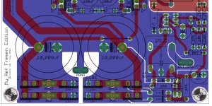
If this ground return should be isolated I think it would be better to connect it to the supply origin, so to have a shorter return path and to avoid radiation, like this:

It's easy to implement, preserve actual layout and should be, hopefully, effective. 😉
Do you think it would be a good solution?
I wasn't sure it was needed ot not so I left it but, in fact, I'm not using it since it sound worse when it's connected to safety ground.
If you confirm it's not needed I'll be happy to remove it. 😀
I kept the ground plane as intact as possible for this reason, I've slotted only bridges planes since it was pretty easy to identify return current and to better isolate diodes spikes.
The PCB specifications already include 70um copper for higher current capability so, indirectly, the magnetic field pick-up should be minimized.
I'll try the EI trasformer trick to confirm.
You're welcome 🙂
thanks for suggestions. 🙂
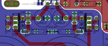
Because of the dual bridges the ripple current in the big caps probably is not that much of an issue (decoupled returns there already), but I found a little bugger that has its ripple current going right through the signal/load return path, C14.
In fact I thought about it...
If this ground return should be isolated I think it would be better to connect it to the supply origin, so to have a shorter return path and to avoid radiation, like this:
It's easy to implement, preserve actual layout and should be, hopefully, effective. 😉
Do you think it would be a good solution?
BTW, what's the reason for the PWR_GND tab? I would think it is not needed for anything other than center-tapped. But, then the relay supply would need a little change, too....
I wasn't sure it was needed ot not so I left it but, in fact, I'm not using it since it sound worse when it's connected to safety ground.
If you confirm it's not needed I'll be happy to remove it. 😀
Regarding large GND planes, those can be dangerous because they can pickup magnetic fields which will cause rotating eddy current that in turn will create small voltage drops. (...) With 70u or 105u copper one can lower that with brute force, though, still broken/slotted planes are the more clever approach (but can easily go wrong if one has overlooked a current path).
I kept the ground plane as intact as possible for this reason, I've slotted only bridges planes since it was pretty easy to identify return current and to better isolate diodes spikes.
The PCB specifications already include 70um copper for higher current capability so, indirectly, the magnetic field pick-up should be minimized.
I'll try the EI trasformer trick to confirm.
Thanks for the 5.x files, they do open now. I'm gonna play with them tomorrow...
You're welcome 🙂
Attachments
Dario, Did you ever give more consideration to eliminating C102/202?
Hi Bob,
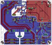
I've made a version without them and Caddock only for R104/R204 but after having made place for both MK132/0309 resistors a void has been created among the two regs (positive and negative).
In this context having C102/C202 or not makes little or no difference to the layout so I choose to leave the option. 😉
Attachments

US Capacitor Suppliers?
@bcmbob
Bob,
Since you seem to have bought all of the standard, optional, plus other choices for caps and resistors, would you mind sharing where you bought them? Dario's BOM is the bomb, but I am having trouble finding some of the caps without shipping them from Europe. In particular, the Elna's in C1 and C2, the True Coppers, and maybe a good price on the Mundorfs.
Here is where I admit to being cheap, or at least wanting all the best stuff without paying too much.
I hope you had a good holiday.
Jac
I would keep C102/202 at any rate, because the shunt regulators are very simple design with little feedback available for regulation. BC639/640 are no gain monsters (and identical with BD139/140 which have more power dissipation capability). To improve regulation try use high-gain selections of the transistors (-16 suffixes) and use two 6.8V zeners at 20mA in series instead of that pretty non-standard 14V zener. 6.8V zeners usually have the best impedance charatersitic and the strongest knee.
Since a shunt reg is only two terminals there is no need for complementary devices btw, same with the current sources.
As for a magic cap, simulation will show at least which capacitor values and parasitics are *not* suitable because these caps afford additional compensation of the shunt regs. Look at the TL431 datasheet for what I mean (only some capacitor values make the TL431 well behaved, others cause oscillation).
I might try to hack the whole amp into LTspice (including estimated parasitics) and see what comes up there....
Last edited:
Hi Jac, Unfortunately the True Copper caps can only be ordered from Germany as far as I know. That's the hardest part in the decision to buy them. ~$60 for the caps - $97 with shipping to the U.S.
Many/most of the top parts came from Parts ConneXion - The authority on hi-fi DIY parts and components
The Rinken resistors came from Angela Instruments Online Catalog - Resistors - Riken Ohm Resistors
A few item came from Dario as samples and he can tell you what's available.
If several builders in a country can agree on what to buy, some bulk savings and lower shipping charges might be a possibility with a group purchase. That works both ways. I can buy from Angela to avoid International charges and distribute via snail mail - $4.5 vs ~ $50.
Last edited:
I am having trouble finding some of the caps without shipping them from Europe. In particular, the Elna's in C1 and C2, the True Coppers, and maybe a good price on the Mundorfs.
Like for the beta GB I can include the four RJHs for ca 4€ more.
I would keep C102/202 at any rate, because the shunt regulators are very simple design with little feedback available for regulation.
I do agree.
To improve regulation try use high-gain selections of the transistors (-16 suffixes) and use two 6.8V zeners at 20mA in series instead of that pretty non-standard 14V zener. 6.8V zeners usually have the best impedance charatersitic and the strongest knee.
They're already specced as -16 version 😉
I'll check for that zeners.
I might try to hack the whole amp into LTspice (including estimated parasitics) and see what comes up there....
It would be interesting but you'll need more complete models of both LM318 (which must includes compensation pins) and LM3886.
Siva seem to have the most 'working' simulation so far.
Klaus, do you think the attached layout is suitable to address the GND problem with C14?
Attachments
Last edited:
Yep that's fine, I think.
A good idea is to provide some SMD pads at various places accross the gap, then you have the option to short it if doesn't work out, either with wire stubs or with SMD capacitors (to provide short HF returns). Easiest way would be to take away solder stop there all along the gap, at least when you have a potent soldering iron.
For sim I'd just use the generic approach of opamp models, as no realistic models of LM318 and LM3886 seem to exist (for LM318 I found none that implements the compensation options). But I'm more after supply/parasitic/routing issues than detailing chip behaviour.
As I said, I don't think it is needed to do much to the PCB in its current state, and my experience tells that you need to fine-tune the actual build anyway with proper measurement tools (which I have access to) if one is after best achievable (measured) performance, even after decades of PCB routing I still run into the need of doing so, any fully optimized PCB tends to need some 2..3 iterations.... one always is overlooking some minor things or is making false assumptions on the order of magnitude their effect will be.
With a full-blown explicit redrawing (and simulation) of the circuit to identify/seperate each and every current loop (both sending and receiving ones) and exposed high impedance points one can get quite far before any real building but that really is a time-comsuming task, taking days usually.
So, let's go ahead with the PCB now... it will work pretty well as is. 🙂
Yep that's fine, I think.
(...)
So, let's go ahead with the PCB now... it will work pretty well as is. 🙂
Fine 🙂
I like the new ground separation and it will be included; if you confirm that the PGND faston is useless I would like to remove it, excluding a potential antenna...
A good idea is to provide some SMD pads at various places accross the gap, then you have the option to short it if doesn't work out
The ground mod seem minor to me, I don't expect any problem, don't you agree?
I'm not enthusiast at the idea of providing shorting pads.
As I said, I don't think it is needed to do much to the PCB in its current state, and my experience tells that you need to fine-tune the actual build anyway with proper measurement tools (which I have access to) if one is after best achievable (measured) performance
I do agree, beta boards are already great performers (subjectively, since I don't have proper instrumentation).
RC ones had a lot of small changes but layout is basically the same, apart the ground mod you inspired.
Like for the beta GB I can include the four RJHs for ca 4€ more.
I'm in for the RJH caps. For me, that's 2 pairs of boards.
As for Klaus' idea of two 6.8 volt zeners, that sounds like a good idea, if feasible. There was a long discussion/evaluation round early in the Salas shunt regulator thread. What I took away from that thread was that zeners less than 10 volts had less noise and sounded better than zeners in the 12 to 18 volt range. In the end, they decided that a resistor with some LEDs in series sounded good, but were had more temperature drift. For low voltage drift, a zener approach is preferred. Here is the Salas shunt build guide which explains the choices, if not the sound.
https://docs.google.com/open?id=0Bz_NDl8g9I4fNVVaT1pvcmpEeVE
I started to build a simulation in CircuitLab. I ran into trouble when I added the transitors, probably something I did wrong. CircuitLab is much more limited than LTSpice, but if anyone wants to play with it, here is the model I started. You can play with on my account or create a CircuitLab account, then copy and paste it to your account. I tend to build and check from the source toward the load, so there isn't anything in the way of a load.
https://www.circuitlab.com/circuit/m2qq76/fe-regulator/
Invoices sent
I've just sent invoices to everyone.
I was still in the middle and Bob paid! Thanks Bob, blazing fast! 😎
I've billed 30€ for each set of two boards.
Shipping fees as previously posted (who ordered 2 sets had 2€ more for the added weight).
The total was then multiplied for 1.034 (PayPal fees) and rounded to the nearest 50 cents.
For additional parts like Elna RJHs or maybe NOS ERO KP1834 a second invoice will be sent after interest posts.
Payment Race
Well, two partecipants already paid.
Let's see how the race goes... 😉
Well, two partecipants already paid.
Let's see how the race goes... 😉
- BMCBob
- SoIL4x4
"The Race" was yesterday and guess who won - Dario 😀
I will arrive last... since I'll pay in the moment I'll submit the order... 😉
Bob, did you see I've added the power LED as you asked?
Thanks, Now if I can find those gold plated male and female fastons for the signal out and returns I'll be a happy camper. I tried a Mouser number you posted but they were still tin. Someday I'll probably make a permanent solder joint at those two spots. Don't know how much difference it would make but gold always impresses.🙄
BTW, I was referring to the Indy race (Mr.Franchitti) and those cars don't have CD players or FEs. - yet 🙂
BTW, I was referring to the Indy race (Mr.Franchitti) and those cars don't have CD players or FEs. - yet 🙂
Last edited:
I'd keep it, you never know. To have an optional connection at the star GND is not a bad idea at all. Why? You can divert leakage current from the source device (preamp/cd) directly with an additional thick(!) cable, then low frequency voltage drops along the signal cable (and the 1R's) are eliminated. You'd need similar access points at the source device, too, ideally. Did help several times, especially with earth grounded sources on bigger power amps which have high coupling to the mains (and therfore I prefer EI-transformers to toriods inspite of their higher magnetic stray field and higher sag under load, in fact I like quite lossy, low bandwith supplies if I can afford the loss).I like the new ground separation and it will be included; if you confirm that the PGND faston is useless I would like to remove it, excluding a potential antenna...
As for the gap for C14, I don't mind if you decide to keep it or not, or include the shorting option or not. I intend and expect to modify the PCB anyway (Dremel tool etc) in the evaluation process at various points (hope you don't mind that it will look quite 'destroyed' afterwards).
- Status
- Not open for further replies.
- Home
- Amplifiers
- Chip Amps
- My_Ref Fremen Edition - Beta build/Fine tuning