Update
Members that still have to send info:
Well... C7 has been changed, now again Vishay KP1380.
Updated BOM, PCB layout and schematic are available on RC Google folder
Members that still have to send info:
- billo44
- TjongKristian
- arthur
- Pmeade
The BOM is final (maybe... 😉 ) for the Mouser part, still in progress for the 'Suggested Best Part' AKA audiophiles/boutique parts.
Well... C7 has been changed, now again Vishay KP1380.
Updated BOM, PCB layout and schematic are available on RC Google folder
Would you attach all the relevant files to this Forum?I've updated Release Candidate Google folder with latest schematic, PCB and Eagle files.
Would you attach all the relevant files to this Forum?
Sure Andrew,
but I don't post all single updates, from time to time I attach major revisions.
You can find the latest I've posted here.
Found them in post501. Thanks
You're welcome Andrew 🙂
How about adding post591 to the post1 index?
This last part of the thread should probably belong to a new thread.
In fact when I'll receive RC boards I'll open a new thread dedicated to the Release Candidate and the opening post will have attached all relevant documents and links to related threads.
Squalor - did we loose you? Please let us know if you are making any progress and/or need some more help.
Hope the music festival was a big success.
Hope the music festival was a big success.
Members that still have to send info:
Tomorrow is the deadline.
Monday I'll begin to send PayPal invoices
- TjongKristian
- arthur
Tomorrow is the deadline.
Monday I'll begin to send PayPal invoices
Squalor - did we loose you? Please let us know if you are making any progress and/or need some more help.
Hope the music festival was a big success.
Rumors of my demise are greatly exaggerated. The music festival brought 80,000 people to our tiny island of Gulf Shores, Alabama. Headliner was the Red Hot Chili Peppers with around 30 other bands, country & rock. I like jazz myself, not that I could go anyway. $200 tickets . I'm working 12 hour days, not much spare time but I have been following this thread.
I was given a commercial paper towel despenser, stainless steel construction that I think could make a fine amp chassis, the benefits of steel but non-magnetic.
One FE board is working again. I will turn my attention to the other one on Monday. I'm holding off buying parts thinking I may get some things for my DCB1 pcb. I hope when the FE group buy is done, Dario will turn his attention to a premium BOM for the DCB1. I would also like to learn about your pre-amp.
Hey, there is no limit on the amount one should pay for a good jazz concert😀
Glad to hear the one amp is back in operation. We are all anticipating the results from the new builders.
If you mean me ... I still using a bare pot from the Mini2496 DAC. Hopefully I will be able to pull the Lighter Note from it's current home this weekend to test it with the FEs. The amps are still at a reviewers store and I probably wont get them back till early next week.
later......
Last edited:
Rumors of my demise are greatly exaggerated.
Pheew! 😀
I hope when the FE group buy is done, Dario will turn his attention to a premium BOM for the DCB1.
For sure I need to do it since my DCB1 still doesn't sound as plain pot...😉
If you mean me ... I still using a bare pot from the Mini2496 DAC. Hopefully I will be able to pull the Lighter Note from it's current home this weekend to test it with the FEs.
I was asking about your JC-2 , where can I read more about it ?
Here is a link to the kit I bought.
Symmetric Complementary J-FET preamplifier JC-2 kit ! | eBay
At that cost and quality it's almost a no-brainer.
This is the original manufacturer.
Product Lines > Halo > JC 2 Two Channel Preamplifier
Uriah got a chance to compare the real thing as produced by Parasound to the Lighter Note and couldn't hear much difference at all. The eBay supplier has reported several people replacing really high dollar pres with this kit. Remember, I used the JC-2 primarily for its gain, and a pre may not be necessary with some speakers. The Lighter Note is super clean but offers attenuation only. In fact, with the upgraded FEs combined with the output on the Mini DAC, the SPL is much higher and a bare pot might be sufficient for many builders. The minimal system - CD player -> bare pot -> FE sounded quite good for analog signals.
Last edited:
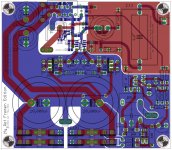
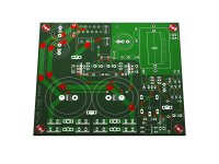
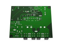
Some images
I've attached some renders and PCB layout.
During the forthcoming week there's still the possibility to made small adjustments to the PCB, post any desiderata/improvement so that I could evalute and implement it.
I've attached some renders and PCB layout.
During the forthcoming week there's still the possibility to made small adjustments to the PCB, post any desiderata/improvement so that I could evalute and implement it.
Attachments
Lookin' Good
The renders look great. They help a relative noob like me better visualize what we are doing here. I only wish my solder job would look as good as the renders.
It doesn't mean much, but I'm happy with the direction you are heading.
Going back to post #590, you suggested 47R Caddocks in the power supply for someone like me who wanted to power another opamp from the regulator. Just in case anyone else needs this idea, I found 47R MP915s available at Digi-key. Now I just have to find enough other components at Digi-key to make it worth an order.
The renders look great.
(...)
It doesn't mean much, but I'm happy with the direction you are heading.
Thanks 🙂
Going back to post #590, you suggested 47R
(...)
Now I just have to find enough other components at Digi-key to make it worth an order.
Not much of a concern, I think you'll be fine with 50R, BTW you can buy from Digikey a lot of parts (Caddocks, Susumus, National opamps, etc.)
PS
40R, also available from digikey, would probably be a better choice.
Last edited:
Dario,During the forthcoming week there's still the possibility to made small adjustments to the PCB, post any desiderata/improvement so that I could evalute and implement it.
Well, the grounding scheme has room for improvement, as the star point scheme is not truly implemented.
The reference GND point is between the two 220uF's, all the smothing cap's GND returns should route to one side of that point while the load return should route to the other side and the small signal GND should return again a bit farther away. See the conceptual schematic from D.Self's power amplifier book.
In your current layout, the ripple current in the big 10mF's flows through a route that is shared with signal and load GND, the signal sensing point is the low end of the 1R, just on the opposite side of the PCB and the load GND is the GND contact of the relay. I've never been a friend of those 1R's "isolation" resistors anyway, especially in a dual mono approach they are never needed IME and only will cause trouble (any voltage drop accross them is an input signal).
I prefer to place the power chip in the center of the board and use a L-shaped aluminum profile to mount to the heatsink, this gives much more room for proper layout.
Also, some series resistors and smoothing caps before the LM317/337's would to fine to get more PSRR on the small signal supply. Further, a ballast resistor between the LM317/337 outputs could help increase current through them for better regulation (100mA++ is what they like best) while keeping the current in the shunt regs low. Does not work with dual LM317 approach though.
Finally, I'm not a big friend of individual bridges on the secondaries, I found center tapped to work better (less disturbed leakage current) and I often use a series resistor in the center tap as well (0R47 is OK).
BUT me thinks, all this would be such a major redesign effort for bascially non-system-critical issues (as the design is working in the real world without big trouble as far as I can see), both conceptually and in layout, so that'll be better done in a new, seperate project....
... maybe except for the GND thing.
I can't open your EAGLE files as I'm using an older version but I'll try some photoshopping to illustrate the point.
Wow Klaus!
this is the sort of feedback that was needed in the design phase but it lacked a bit...
In fact the circuit don't have a star ground, it rely on the ground plane.
Previous versions had an hybrid approach (star ground/ground planes) but some forumers suggested to rely on a single big groundplane.
That approach seem to works pretty good, though, it's even more quiet than a stock My_Ref.
I'll see your photoshop work with interest.
If you want PM me your email address and I'll send you 5.x Eagle files of a previous version (which is pretty similar), or you can download Beta version Eagle files here.
EDIT:
I've made a 'Latest 5.x' folder with latest 5.x files under the RC folder.
Last edited:
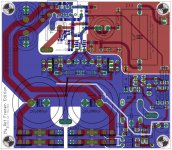
OK, here my suggestion :

Because of the dual bridges the ripple current in the big caps probably is not that much of an issue (decoupled returns there already), but I found a little bugger that has its ripple current going right through the signal/load return path, C14.
If rewired for center tapped transformer the issue would be bigger, that's why I extended the slot a bit to the left to keep the cross currents away.
BTW, what's the reason for the PWR_GND tab? I would think it is not needed for anything other than center-tapped. But, then the relay supply would need a little change, too....
Regarding large GND planes, those can be dangerous because they can pickup magnetic fields which will cause rotating eddy current that in turn will create small voltage drops. A test is to use a tape head demagnetizer (or a loaded EI core transformer) and check if hum levels increase. With 70u or 105u copper one can lower that with brute force, though, still broken/slotted planes are the more clever approach (but can easily go wrong if one has overlooked a current path).
Thanks for the 5.x files, they do open now. I'm gonna play with them tomorrow...
Attachments
Last edited:
- Status
- Not open for further replies.
- Home
- Amplifiers
- Chip Amps
- My_Ref Fremen Edition - Beta build/Fine tuning