Need to pay attention on the cap as it will influence the sound,although a careful design will avoid this.
Hi.
My idea is to improve my old amplifier (Philips 50W). I have two pcb and power supply +35-35V.
Other reason is: Aksa, DX and other amplifiers have bootstrap.
Yamaha have any amplifiers witch bootstrap (Ax392, RX795. RX-V1400-2400...).
Good sound?
My original amplifier is in the other thread: No Miller cap, double bootstrapping.
GEirin
Hi Hugh.
Thank for you reply.
Yes, looks a lot like a Aksa, and DX, old Sansui, Yamaha.... output Roender.
My version is "ecleptical" lin topology amplifier.
Regards
Guillermo
Thank for you reply.
Yes, looks a lot like a Aksa, and DX, old Sansui, Yamaha.... output Roender.
My version is "ecleptical" lin topology amplifier.
Regards
Guillermo
Hi,
what is the purpose of r16 (47k)?
R13 (1k0) looks a bit big for a range of bias currents.
Why the input bootstrap (r5)?
I would expand the NFB/stability options by adding an R+C parallel to that lone C8 (5pF)
what is the purpose of r16 (47k)?
R13 (1k0) looks a bit big for a range of bias currents.
Why the input bootstrap (r5)?
I would expand the NFB/stability options by adding an R+C parallel to that lone C8 (5pF)
Hi, GEirin,
Nice design 😀
I experienced that C3 makes the amp unstable (unless you make it some R series to C3). What is the purpose of C3?
Also, what is the difference if Q5-Q7 is made darlington, not CFP?
Nice design 😀
I experienced that C3 makes the amp unstable (unless you make it some R series to C3). What is the purpose of C3?
Also, what is the difference if Q5-Q7 is made darlington, not CFP?
Good ideas Geirin.... you are selecting many good ideas and using them together
C3 will work better with a resistance in series.... 22 ohms for instance.
C8 is a nice idea..used by Sansui into model 517 and 717.
Good ideas together use to produce nice sonics.
regards,
Carlos
C3 will work better with a resistance in series.... 22 ohms for instance.
C8 is a nice idea..used by Sansui into model 517 and 717.
Good ideas together use to produce nice sonics.
regards,
Carlos
Hi all.
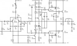
R16: Load resistor, for to limit the Vas gain.
R5,R7,C4 network: for to stable the diff input.
C8: Phase lead capacitor, for frequency compensation.
R9,C6: Filter Vas input, for no to use miller compensation
capacitor.
D1, R15 network: for reduce cross conduction and protects the drivers transistors.
I will study the comment for improve my project.
Thanks
Guillermo
Hi Geirin,
Nice circuit; simple, effective, musical.
Can I ask why you use FETs for drivers, rather than bipolars?
Isolation from a reactive load? If so, maybe it's a good idea......
But you could more cheaply achieve this isolation with a bipolar driver such as a 47943/1837 and keep the Vbe of the predriver more constant for superior linearity.
You should be able to run your VAS at a lower current, too, around 6mA. Keeps dissipation lower in the VAS and reduces the lag comp constraints.
I don't believe dissimilar voltage supply rails are needed; use the output stage to clip, not the negative swing of the VAS.
Cheers,
Hugh
Hello Hugh.
Thanks you very much for you reply.
Why mosfet drivers? Because in the other thread "RMI-FC100" (Roender), in post 66 you said "Your output triple is good, but I´d
try replacing Q1/Q3 with low current thermally robust mosfet, say IRF 710 series.... And I think, good idea.
I´m a diy, but not an expert in amplifier designer, I´m Industrial Designer and diy audio is my hobby.
You think: a bipolar driver such as 2sa1837-2SC4793 is the best. OK. I will use it.
Sorry, any questions:
1- What is your opinion of the Sziklay VBE multiplier?
2- Stopper resistor in predriver: yes or not?
Regards
Guillermo
Attachments
Hi, GEirin,
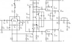
If you aim for isolation, will it be better if the mosfets are placed for Q6-Q7, instead of Q8-Q9?
If you aim for isolation, will it be better if the mosfets are placed for Q6-Q7, instead of Q8-Q9?
Hi Guillermo,
My pleasure. Remember, I only have an opinion, and nothing is more dangerous...... I may well be wrong.
I don't enjoy it when people throw back what I said weeks or months ago!! Posts don't convey this well, but consider that I might have been saying one thing but meaning just the opposite; this is common with Australians.
Steve McCormack, a famous US designer, uses mosfets as drivers too. His response is that it gives excellent isolation, but his configuration is, AFAIK, source follower then emitter follower.
However, the advantage of the CFP as used also by Mihai is that the input impedance to the predriver, the 3423/1360, is VERY high, on the order of megohms, so loading on the VAS is much reduced. This is very important.
But it's a little higher with a little less local feedback using a mosfet than it is with a bipolar, and the distortion introduced by Vbe variations will be less with bipolar.
Lastly, consider the cost factor. I think the 4793/1837 combination I suggested could be cheaper and more robust during manufacture than the mosfet......
I could not say about the Sziklai Vbe multiplier. This is usually a critical part of bias stability for CFP output stages, though this stage will be more forgiving because the base/emitter of the output devices is in the thermal loop, unlike a two device CFP. A standard Vbe multiplier might be too enthusiastic; you'd need to put a resistor into the emitter circuit as you have done. Finding the best value for this resistor would depend on thermal coupling with the output stage and you would need to arrive at the values empirically. I think a diode is not a good idea as it shares a similar tempco to the Vbe junction and this would double the slope of the Vce variation with temperature.
A stopper in the predriver of 100R is a very good idea.
Hope this helps,
Hugh
Hi, AKSA,
I've been wondering about this too. If we swap Q8-Q9, then it becomes a darlington driver. How about the input impedance of this (darlington driver) compared to CFP driver, is it about the same or quite different?However, the advantage of the CFP as used also by Mihai is that the input impedance to the predriver, the 3423/1360, is VERY high, on the order of megohms, so loading on the VAS is much reduced. This is very important.
lumanauw said:Hi, AKSA,
I've been wondering about this too. If we swap Q8-Q9, then it becomes a darlington driver. How about the input impedance of this (darlington driver) compared to CFP driver, is it about the same or quite different?
David,
Did you receive my e-mail regarding this question?
Mihai
Yeah.... this one will sound great.
A good idea to construct to evaluate real world hermano!
muito bom.... felicitaciones.
regards,
Carlos
A good idea to construct to evaluate real world hermano!
muito bom.... felicitaciones.
regards,
Carlos
- Status
- Not open for further replies.
- Home
- Amplifiers
- Solid State
- My update lin topology