Post 26
Hi MJL.
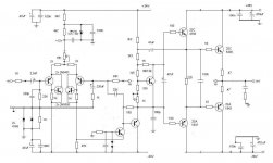
Thanks for you recommendation. Why a single device VAS? In post 26, my circuit has a 2SC3423. What is your opinion?
Hi MJL.
Thanks for you recommendation. Why a single device VAS? In post 26, my circuit has a 2SC3423. What is your opinion?
an interesting very low distortion (in sim) design using some of this threads concepts:
http://www.diyaudio.com/forums/solid-state/134604-hi-loop-gain-amp.html#post1680729
http://www.diyaudio.com/forums/solid-state/134604-hi-loop-gain-amp.html#post1680729
In my point of view the schematic in post 26 is fine too
I have tried both VAS circuits.... the two stage unit gave me more bass, more power, more controlled bass.....but i missed the loosen bass i had with the single stage VAS.
I have not tried to load the VAS.... and Hugh told me,once and a long time ago, to give a try on it... a capacitor and a resistance to ground...loading the VAS output... this may change the harmonic spectrum a little.
Those parts can go in series or in parallel...i would prefer series not to disarrange the VAS operating dc current...to load to AC only.
regards,
Carlos
Last edited:
Despite i have born Christian i am not fanatic.... Doctor Self book is not my bible
What he use to say may be a reference.... his book is very good, he is excelent, but i have some different points of view...there are some controversies about a lot of things..reason why i use to build and test.
I do not follow ideas alike religion...i am not a believer...my faith can be the results from comparative tests...to electronics this is my handbook, my bibble... to check everything, to believe no one and nothing.
Test your ideas i suggest..and compare one and other with a reference..or you gonna be lost..never knowing if one is better or worse.
All we do, related evaluations, because we are humans, because we have pride, because we have Ego...is to do mistakes!....Also we are arrogant... we think that all we do is good and better than things made by others, or better related what we have made before.... our modifications are always understood as "advantage"...because those are our spectations and this "makes our mind" ... and i could see that happening many times. with several people, including myself.
Knowing we fool ourselves we gonna be prepared to defend ourselves against our own foolish.
I could see, realise, conclude, many times... the oposite... we think things we make are better and in the reality they were not!....so....we need to disconnect ourselves from the system and try fair testing because we are extremelly biased and a awfull tool to evaluate things.... do comparative and do blind..or you will be walking in circles or marching in the same place, delirating that have made progress.
Related what is written by this or that author, do not believe that as truth..even because the author can change his mind...and will keep this same idea. written there. not to be ashamed to say was wrong...and we gonna be following wrong rules..things the author could have abandoned and replaced by other better ideas.
regards,
Carlos
Last edited:
Hermano Destroyer X.
Mr. Self no es mi Dios, pero..............(Mr Self is not my God, but..............)
Mr. Self no es mi Dios, pero..............(Mr Self is not my God, but..............)
no és mi dios......pero...... usted tambien!
de acuerdo.
mui bien.
Carlos
Doctor Self is not my god!...but you are not also.
You have agreement hermano.
all rigth.
Carlos
de acuerdo.
mui bien.
Carlos
Doctor Self is not my god!...but you are not also.
You have agreement hermano.
all rigth.
Carlos
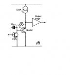
Here VAS + Buffer and buffer +VAS + buffer.
A triple has the same buffering effect. Only 10uA VAS load at 500W / 2R.
By DX - I have not tried to load the VAS
By using a triple , all that is left for a load is one that is passive (r or r/c) , I do use 100k - 220k to passively load my VAS'es and one can tweak the "sound" (purely subjective) by just changing the value. A far larger change to the sound is to cascode the VAS.
OS
Last edited:
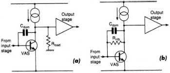
Is there a specific reason why in post2 #33 & #34 the bootstrap cap is connected to the driver output istead of the final output?
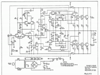
Stevens says of the Phase Linear PL400
"I think the main reason for connecting C11 to the emitter of the driver is that this emitter voltage follows the AC signal on the collector of Q5 much better than the output does, so the voltage across R18 is kept more constant and the collector impedance of Q5 becomes higher and more linear. I think even harmonic distortion is lower because the half wave rectified (class B) non linearity of the voltage across emitter resistors R40, 43, 45 is not fed back."
"I think the main reason for connecting C11 to the emitter of the driver is that this emitter voltage follows the AC signal on the collector of Q5 much better than the output does, so the voltage across R18 is kept more constant and the collector impedance of Q5 becomes higher and more linear. I think even harmonic distortion is lower because the half wave rectified (class B) non linearity of the voltage across emitter resistors R40, 43, 45 is not fed back."
Attachments
Member
Joined 2009
Paid Member
GErin,
My vote: I like the buffer + VAS, this was where TGM was headed. It allows some interesting options with Cdom and it simulates very nicely. I believe it has the possibility to retain the Bootstrap sound that is key.
I hope you will try the experiment and build this kind of VAS as I have little time these days and have been interested in trying it out for ages 🙂
Hi Bigun.
Thanks for you reply. I have litle time also. I will try your recommendation.
Your vote is: CFP input + buffer - VAS + CFP driver + EF output?
Guillermo
Thanks for you reply. I have litle time also. I will try your recommendation.
Your vote is: CFP input + buffer - VAS + CFP driver + EF output?
Guillermo
Member
Joined 2009
Paid Member
Hi Bigun.
Thanks for you reply. I have litle time also. I will try your recommendation.
Your vote is: CFP input + buffer - VAS + CFP driver + EF output?
Guillermo
Yes !
Actually, I'm also quite interested in CFP for the power output, but I have mixed feelings on this and I'm still reading and learning about the use of CFP in the output. My thinking is that CFP is the ultimate configuration but it works better in Class A. By using it for the driver stage you operate it in Class A and get lots of benefits.
I partly blame my love of the CFP on Lumba, who encouraged me early on during my formative learning stages to look at them... 🙂
Hi
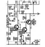
It might be prudent to have the same Vce (Pd) on Q4 as on Q3. This can easily be accomplished by adding a PNP transistor cascode to Q4's collector wrt GND. The collector of Q4 to its emitter, base to GND, collector to the diodes where Q4 collector is now.🙂
It might be prudent to have the same Vce (Pd) on Q4 as on Q3. This can easily be accomplished by adding a PNP transistor cascode to Q4's collector wrt GND. The collector of Q4 to its emitter, base to GND, collector to the diodes where Q4 collector is now.🙂
post #51
Q3 Vce is 75V, and Q4 Vce extends all the way to the negative rail. Assuming the current is ~equal, Pd would be twice that of Q3. Vbe is affected by temperature, so you would want it the same for both devices, no?
Q3 Vce is 75V, and Q4 Vce extends all the way to the negative rail. Assuming the current is ~equal, Pd would be twice that of Q3. Vbe is affected by temperature, so you would want it the same for both devices, no?
Last edited:
GEirin,
very nice. I would remove the CC stage after the VAS and that 180pF cap. Consider active current sources.
very nice. I would remove the CC stage after the VAS and that 180pF cap. Consider active current sources.
Member
Joined 2009
Paid Member
- Status
- Not open for further replies.
- Home
- Amplifiers
- Solid State
- My update lin topology