Hi Linuxguru.
I will need to arrive at the values empirically for R16; C5; C11-R22.
Regards
Guillermo
I will need to arrive at the values empirically for R16; C5; C11-R22.
Regards
Guillermo
Guillermo,
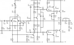
Try adding 10R of emitter degeneration in Q6 and Q7. This will improve linearity, reduce OLG around the Sziklai pair (already VERY high), reduce bias sensitivity somewhat, and increase input impedance to the Q6/Q7 bases, lightening the load for the VAS.
Otherwise, it's looking good. You will certainly have to fiddle with R16 as LXG says because it will set the slope of the tempco, which is important as only the outputs should be in the thermal loop.
I like it a lot. Simple and very musical. You must design a nice pcb and build it. Up there with the DX amplifier!! Very important to have a long, careful listen.
Congratulations!
Hugh
You have very good people around helping you Geirin
Your amplifier is still very good and will be even better if you accept some of those suggestions people are posting.
I like you ideas...you were selecting, analising and concluded very good things.
Hoje em dia está muito difícil criarmos idéias originais.... muita gente já pensou em muitas coisas....hoje em dia temos mesmo é que selecionar bons subcircuitos e colocá-los para trabalhar juntos, e com isso, descobrir quais combinam melhor.
Now a days we have to select subcircuits and put them to work together to select the best combination...original, new ideas, are difficult and hard to have, as thousands of ideas were already published into the internet.... not easy to create a new circuit, that one nobody had never used...so.... the selection of subcircuits, the best VAS, the best differential, and so on, will result fine...the parts selection is also very important.... the last movement, also important, is the testings and biasing tests.... to tune the unit to best bias.
I think you will finish producing a very special amplifier..... will be SS....not solid state..will be Super Special.
regards,
Carlos
Hi all.
Thanks very much for yours replies.
Linuxguru: Sorry. Yes: R16 is 4R7. Error of tiping.
Hugh: Very important you help. I improve my project. One question: stopper R in power transistor? Yes or no?
Hermano Destroyer: You DX amplifier and my project amplifier are SS (super special). Mercosul- Mercosur- Sudamericano amplifiers?
Simples y musicales diyamplifiers.
Below attached update my amplifier.
Opinions?
regards
Guillermo.
Attachments

Hi David,
The input impedance of a double darlington is a function of the beta product and the load. This is not so with the CFP, which thus isolates the driver from the load more completely.
Guillermo,
Yes, 10R base stoppers on the outputs. Very good idea; prevents any short term oscillation due to occasional instances of base negative impedance, particularly with reactive loads.
Hope this helps.
Now, build your amp and tell us how it sounds!!
Cheers,
Hugh
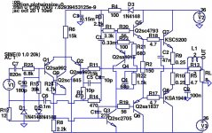
OK, here's something similar, loosely derived from the simplified AKSA schematic posted here a few years ago. I've built a prototype with a few changes from the LTSpice schematic shown (I simulated it with devices for which I had reliable Spice models, and substituted devices with similar specs in the prototype).
The changes are:
Simulated -> prototype
2sa1837 -> 2sa1220a
2sc4793 -> 2sc2690a
2sa1015 -> bc558
2sc2705 -> ksc3953
Edit: The first prototype didn't have R24, Q9 and the miller cap C11. But the gain of the VAS transistor Q3 (ksc3953 in the prototype) is only ~60, so I tried to jack up the open-loop gain with R24 & Q9. That made it unstable in the prototype (although still stable in LTSpice with the 2sc2705 with lower fT than the ksc3953), and it let the magic smoke out of a few resistors, particularly the Zobel. So I bit the bullet and added Cdom, C11. Simulation showed that H2, H3 didn't increase greatly in the range from 12pF to 27pF, but increased by ~10 dB for 47pF. I went with 27 pF, prayed hard and powered it up - no smoke this time! Audible sonics are also exceptional, as suggested by the simulation.
Attachments

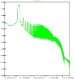
And finally, the simulated LTSpice AC sweep from 10 Hz to 10 MHz:
Edit: I forgot to mention, it is biased in Class-AB at the edge of Class-B, and
sounds quite exceptional - crystalline highs, mellow/open mids, and controlled but not excessively boomy lows (probably sonically similar in some respects to AKSA 55W without the Nirvana+ upgrades).
Edit: I forgot to mention, it is biased in Class-AB at the edge of Class-B, and
sounds quite exceptional - crystalline highs, mellow/open mids, and controlled but not excessively boomy lows (probably sonically similar in some respects to AKSA 55W without the Nirvana+ upgrades).
Attachments

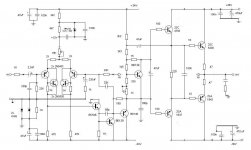
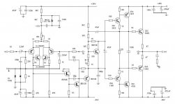
1) The BD139 in the VAS is probably too slow and has a high Ccb - you probably need to use a much faster NPN device like a 2sc2705 or 2sc2240 at that location. The PNP can be just about any medium power device.
2) The bootstrap from the emitter of the upper driver transistor is interesting - I need to simulate it to understand it; I haven't tried that topology before.
2) The bootstrap from the emitter of the upper driver transistor is interesting - I need to simulate it to understand it; I haven't tried that topology before.
Hi Linuxguru.
Thanks for you reply.
"I need to simulate it to understandit". OK.
I can´t to simulate circuit. I wait for you simulate.
Guillermo.
Thanks for you reply.
"I need to simulate it to understandit". OK.
I can´t to simulate circuit. I wait for you simulate.
Guillermo.
Schematic is almost the same we have into the DHR Turbo
And if DHR Turbo sounds fine.. this one will sound fine too.
Coincidence or not... accident or not, you have made (created, calculated) the same amplifier.
All those amplifiers, deeply inspired into the published Aksa 55 simplified schematics, sounds excelent...in special because the bootstrap technologie used to feed current to drivers and output.
You do not need, even to simulate..just do it and will sound very good, distortion will be low and performance very high.
Aksa amplifiers, as source of inspiration is a guarantee!
regards,
Carlos
Attachments
Last edited:
Hola hermano.
Hi.
YES, the inspiration of my lin topology version is a evolution the RCA; Phase Linear; AKSA´s; DX´s; Roender output;TGM and others amplifiers. My actual intentions is to improve the VAS stage.
Saludos
Regards
Guillermo
Hi.
YES, the inspiration of my lin topology version is a evolution the RCA; Phase Linear; AKSA´s; DX´s; Roender output;TGM and others amplifiers. My actual intentions is to improve the VAS stage.
Saludos
Regards
Guillermo
2 things I'm not seeing:
First, the resemblance to the DHR turbo, other than they are both amplifiers.
Second, the improvement in the VAS.
<My recommendation> Try a single device VAS, but make it a good one - fast, low Cob good beta.
First, the resemblance to the DHR turbo, other than they are both amplifiers.
Second, the improvement in the VAS.
<My recommendation> Try a single device VAS, but make it a good one - fast, low Cob good beta.
I do not remember very well if RCA was the first to use
I think and English factory for guitar amplifiers made amplifiers this way first...do not remember the brand and model (for a while)... was around 1969 i think.... well.... very cloudy memories... this was a long time ago.
The VAS was explored too into the Precision 1.... the protection transistor BC547(Q7) and the 22 ohms resistance (R19) was because of Andrew T.... sounds better without that resistance.... he said would be dangerous...the VAS could burn...i have tried and have not burned..but i have included the protection into the schematic, to offer more reliable things to forum folks.
A pity that we have exausted, along those last years, all the options (variations) about the good amplifier topologie...i would like to have something new to assemble.... maybe patchwork will be an option, has interesting differences to explore listening.
Good luck!
regards,
Carlos
Attachments
Last edited:
- Status
- Not open for further replies.
- Home
- Amplifiers
- Solid State
- My update lin topology