Yeah, I think so as well.
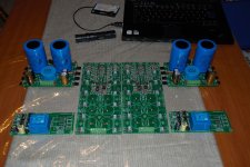
I will build it as is, with the opportunity of doubled output devices.
I will build it as is, with the opportunity of doubled output devices.
I haven't finished compiling the data from this, but Gianluca was kind enough to post his study. My eyeballing of the data shows attached for chassis 3 (5U/500). My Italian is not so good, but it looks like the full chassis was built, and one side (one pair) of the heatsinks were thermally loaded. Excellent data he gave us! I only pulled data up to wattages and temps in the "reasonable" range.
I am working on a summary and some calculations, but this may help for now.
Good luck with your project!
Edited to add link vs. file for original file from Gianluca. File was too big.
https://cdn.shopify.com/s/files/1/1006/5046/files/RELAZIONE_TECNICA_TERMICA.pdf?v=1600673225
I am working on a summary and some calculations, but this may help for now.
Good luck with your project!
Edited to add link vs. file for original file from Gianluca. File was too big.
https://cdn.shopify.com/s/files/1/1006/5046/files/RELAZIONE_TECNICA_TERMICA.pdf?v=1600673225
Attachments
@Gyuri /ZM - check out the temps at 750W per side with the fan... 120C max and 110C on the fins. I need a nice amp / water heater for my coffee and tea. hmmmmmm.
😱
I'll try to get regression / correlation done within the next day or so.
The goal was/is to take the data from different sinks and be able to predict the dissipation for other Modushop heatsinks at various thermal loads. In short, I wanted to see by what amount to de-rate at a given dissipation and try to ball-park for other heatsink sizes. I extracted (by eye) the data for the 4U/400 and what I think is a 2U/400. I also have my own data for the 5U/400 and I'll soon have a 4U/500 to see how it compares in my own use. Not sure how it'll shake out, but we shall see.
I am continuing to work on my Italian. 🙂
I haven't finished pulling out all the data and doing the analysis. However, after a more careful look, I can't assume an ambient of 22C. From the graphs, it looks closer to 27C. That makes a bit of a difference. Revised file attached. Apologies for earlier error.
Mi Dispiace 🙂
I haven't finished pulling out all the data and doing the analysis. However, after a more careful look, I can't assume an ambient of 22C. From the graphs, it looks closer to 27C. That makes a bit of a difference. Revised file attached. Apologies for earlier error.
Mi Dispiace 🙂
Attachments
O.K. then I will post my empirical results, when I ready.
Until then I need to do lots of soldering and tapping work. 😉
Until then I need to do lots of soldering and tapping work. 😉
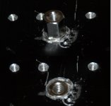
Everybody makes mistakes.
There were a broken tap, and after this, if it wouldn't be enough, a broken drill body.
I corrected it after a while.
Not so beautiful, but at least ugly.
It consumed more time, than to make all of the other threads.
I have found this video, liked a lot: 😀
Broken Tap Removal by Metal Disintegration Machine (MDM) - YouTube
Attachments
This was a heat sink made of aluminum.
It was just a bad move.
I have made 44 threads in blind holes.
Ten was M3, thirty four was M4.
I broke only one, but it needed more work to repair, than make the remaining forty three.
O.K..
I will make yet three other ones, as this one:
It was just a bad move.
I have made 44 threads in blind holes.
Ten was M3, thirty four was M4.
I broke only one, but it needed more work to repair, than make the remaining forty three.
O.K..
I will make yet three other ones, as this one:
Attachments

I didn't mentioned yet, some of the blind holes aren't blind anymore, because I carried out some unintentional eye surgery.
Next ones will be better, because I measure, and measure....
Next ones will be better, because I measure, and measure....
I've made a mistake.
At the frontend, I've soldered first BC550s instead of BC560s.
It was mostly because of my dimmed eyes.
No, it wasn't because of beers, but I really can't see clearly if things are too close.
Fortunately, it didn't caused smoke, only I wasn't able to set single ended offset to zero.
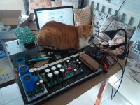
Anyway, I'm trying to be careful for first power on, there is a big help for it. (Other than Emil the cat.)
It is one of my best equipment, I simply love it:

At the frontend, I've soldered first BC550s instead of BC560s.
It was mostly because of my dimmed eyes.
No, it wasn't because of beers, but I really can't see clearly if things are too close.
Fortunately, it didn't caused smoke, only I wasn't able to set single ended offset to zero.
Anyway, I'm trying to be careful for first power on, there is a big help for it. (Other than Emil the cat.)
It is one of my best equipment, I simply love it:
Are you sure that 3.5 kVA from that humongous isolation transformer will be enough to drive your amp? 
Gotta love that honker. Lifting only with diapers on. 😀
Good luck with firing up
Gotta love that honker. Lifting only with diapers on. 😀
Good luck with firing up
Actually, it works.
Initially I followed original schematic, and voltages.
https://www.diyaudio.com/forums/attachments/pass-labs/901481d1607873302-ugs-power-amplifiers-french-connection-ugs-power-amp-schematic-pdf
I set my Schuntermann to output about 182VAC, in this way I've got 23VDC for output stage, and 30VDC for frontend.
Everything is fine, after I've changed those BC550s to BC560s, what I've put in a wrong place.
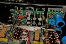
But I have a strange problem, what I can't resolve.
Differential DC protection switching on and off constantly at about once/second.
Any idea, what is going wrong?
(On this picture you can see my not so ideal solution for this problem.)😉
Initially I followed original schematic, and voltages.
https://www.diyaudio.com/forums/attachments/pass-labs/901481d1607873302-ugs-power-amplifiers-french-connection-ugs-power-amp-schematic-pdf
I set my Schuntermann to output about 182VAC, in this way I've got 23VDC for output stage, and 30VDC for frontend.
Everything is fine, after I've changed those BC550s to BC560s, what I've put in a wrong place.
But I have a strange problem, what I can't resolve.
Differential DC protection switching on and off constantly at about once/second.
Any idea, what is going wrong?
(On this picture you can see my not so ideal solution for this problem.)😉
Attachments
Last edited:
Congratulations !
My DC protection board did that when I had in- and output flipped.
I connected it to the PSU of the amp with ground reference and plus voltage in the correct orientation.
My DC protection board did that when I had in- and output flipped.
I connected it to the PSU of the amp with ground reference and plus voltage in the correct orientation.
Thanks for reply, but I think there must be an other problem, because DC protection is on the main board, so I don't have a chance to connect it wrong.
- Home
- Amplifiers
- Pass Labs
- My UGS UP! power amplifiers - The French Connection I.