cm961 said:Hey Russ,
Great design, I'm going to make some tonight!
Quick question about your PCB making technique. My technique is very similar but without the extra piece of paper (just iron right onto the photo paper). I have a difficult time getting the paper off but keeping the toner on to the copper. Are you saying the toner will stick to the copper and the paper will stick to the photo paper and will pull off all at once? My current method takes hours of soaking and rubbing to get the paper off.
If so I will definitly attempt tonight with the second sheet.
Also you say medium heat, whereas I was using max (1200W iron). Maybe that will help.
Pete
Thanks! 😀
The problem you are having is most likely due to the paper. There are several type of photopaper. Some I used had the same results as yours. Thats why I switched to the jetprint stuff from walmart.
The sheet of paper on top is just plain paper, it is simply there to keep the paper from sticking to the iron. You can tell the good stuff because it will do that, if you heatthe back it will be sticky. 😀 At least that my experience.
I use Press'n'Peel Blue which works really well. Once you've ironed it, you can peel it off and you can see the reverse layout on the "plastic" that you've pulled off. This makes it easy to see if any part of the toner didn't transfer.
It's a little bit expensive (not so much for you guys in the States), but I think its worth it.
I think the cheapest place I've seen it is at Techniks (that's where I got it, and even with the very expensive shipping costs, its still half the price of the stuff over here).
It's a little bit expensive (not so much for you guys in the States), but I think its worth it.
I think the cheapest place I've seen it is at Techniks (that's where I got it, and even with the very expensive shipping costs, its still half the price of the stuff over here).
I may have to try that, but I'll try the walmart paper first since I'm looking for the absolute cheapest method 🙂
Anyone have any advice on removing the toner before etching? Do you have to scrub?
Pete
Anyone have any advice on removing the toner before etching? Do you have to scrub?
Pete

Thanks, just tried it and it works great. Not so much on the boards that I already drilled with toner on them 🙁 haha. Oh well, I just ran off a sheet of 20 of these LM3886 boards. Don't worry I'm not selling them... I need a ton for home theatre 🙂 I'm up to the etching part, I'll let you know how it goes!
Pete
Pete
cm961 said:Thanks, just tried it and it works great. Not so much on the boards that I already drilled with toner on them 🙁 haha. Oh well, I just ran off a sheet of 20 of these LM3886 boards. Don't worry I'm not selling them... I need a ton for home theatre 🙂 I'm up to the etching part, I'll let you know how it goes!
Pete
What worked?
Russ White said:
What worked?
Russ, I assume Pete meant the scotchbrite worked well in getting the toner off?
yeah, and acetone together. i'm out of acetone now but I have not one, but twenty! perfect boards!!
Just drilling now (only 1).
Pete
Just drilling now (only 1).
Pete
Yes I've made a ton of boards now your (g's) method. I even tried to put the component side on after I'd drilled it. But I got some bad news, the scale is slightly off! I'm not sure whether its the component mask or the copper, but the chip fits in the copper just fine, no pins bent or anything, so I must have printed the component side wrong. Also I used just normal paper for the component side, and it actually worked, mostly. I just had it and wanted to try it. In the future I'll use the inkjet photo paper just like I did for the solder side.
I'm still having trouble getting the paper off (trouble = takes forever). Hot water did make it easier, but its still a pain. I think leaving it overnight is the ultimate solution but I'm too eagre. We need to find a chemical which will dissolve the paper quickly but not affect the toner or copper!
Thanks again for the design, I haven't soldered the components on yet but I have 20 perfect boards.
Pete
I just double checked the PDF files, they are correct.
Make sure when you print the PDF you have page scaling turned set to none, otherwise they will not be correct.
I am glad it went well for you! Enjoy! 🙂
Make sure when you print the PDF you have page scaling turned set to none, otherwise they will not be correct.
I am glad it went well for you! Enjoy! 🙂
Yeah I may have had it scaled. Either way it's so close that I'll easily be able to make them work, so I'm not concerned.
The question is, what am I going to do with 20 boards. I'm planning/building a set of studio monitor speakers which will be two way bi-amped, so I need four for that. I intend to make the complete circuits (power supply, preamp, filters, power amps) all on one board but these boards will be great for prototyping. I may use the LM3875 for the tweeters though as I've heard it sounds slightly better.
Pete
cm961 said:Yeah I may have had it scaled. Either way it's so close that I'll easily be able to make them work, so I'm not concerned.
The question is, what am I going to do with 20 boards. I'm planning/building a set of studio monitor speakers which will be two way bi-amped, so I need four for that. I intend to make the complete circuits (power supply, preamp, filters, power amps) all on one board but these boards will be great for prototyping. I may use the LM3875 for the tweeters though as I've heard it sounds slightly better.
Pete
When you get that board designed I would like to see it. 🙂
Maybe I could help? 😀
Sure.
The power amp is based on a 18-0-18 transformer (I think, something close to that). So whatever rails that gives me. Then I need a +15VDC and -15VDC for the preamp.
The preamp will consist of a buffer / attenuator, crossover, linkwitz transform (on the woofer only) and gain adjustment / attenuator on the tweeter.
The amps will be similar to the one you designed, only I'll likely use the LM3875 for the tweeter as I mentioned. I'm also thinking of using a ribbon tweeter. Not sure what to use for the woofer although I'm thinking both will need to be shielded.
Everything mounts to a plate which mounts to the back of the speaker. The exterior side of the plate gets a large heatsink.
There will likely be three knobs: volume, tweeter level, and linkwitz transform level (so that it can be reduced if near a wall or whatnot). There will also be a fuse on the line, and a power switch.
Pete
From experience I can tell you in no uncertain terms that the LM3875 while a good and worthy chip has nothing over the LM3886 in any audio band, bass, mid or trebel. I am not sure where you are getting that. I spent the better part of a week testing that exact (triamplified speaker) scenario at the UT lab.
I would stick with te LM3886 though I am quite certain it will sound fabulous either way. 🙂
I would stick with te LM3886 though I am quite certain it will sound fabulous either way. 🙂
Hmmm thanks for the advice! I suppose I'll just use the LM3886 then. It simplifies the design a little.
Pete
Pete
Hi Russ,
Very nice PCB. I've been trying to learn eagle but haven't produced anything yet. 😉
By chance, I made a little GC very similiar to this one, except I used a t-net for the feedback network. It was just an exercise in making it as small as I could. It's gotten a little ugly after changing the resistors a few times. My conclusion was if you make it too small it is very difficult to experiment with. Once you have the design finalised then its OK. 😀
thanks
Attachments
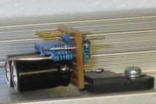
Smallness
The design is finalized here, it is really just the datasheet NI circuit. The funny thing is the "smallness" was never intentional, it just happens to be tiny. I designed it around the size caps I have. Really its not that small, and its easy to work with because everyting lies flat and flush.
Good luck with your design work.
Cheers!
Greg Erskine said:Hi Russ,
My conclusion was if you make it too small it is very difficult to experiment with. Once you have the design finalised then its OK. 😀
thanks
The design is finalized here, it is really just the datasheet NI circuit. The funny thing is the "smallness" was never intentional, it just happens to be tiny. I designed it around the size caps I have. Really its not that small, and its easy to work with because everyting lies flat and flush.
Good luck with your design work.
Cheers!
I know, this topic is old but - what values should be used for RZBL (The resistor) and CZBL (The capacitor)?
- Status
- Not open for further replies.
- Home
- Amplifiers
- Chip Amps
- My tiny single sided LM3886 PCB layout. :)