So, I was thinking of using a lowly Wima polyester .1uF 100V for C6 on the preamp board (diode bypass), rather than a polyprop, as I have tons of them. Since it's just part of the CCS and not in the signal path, shoudn't this be satisfactory?
BrianDonegan said:So, I was thinking of using a lowly Wima polyester .1uF 100V for C6 on the preamp board (diode bypass), rather than a polyprop, as I have tons of them. Since it's just part of the CCS and not in the signal path, shoudn't this be satisfactory?
In that position it may have little effect but remember that all the circuit including the PSU IS on the signal path so testing is requiered for each aplication, in my opinion.
Russ,
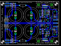
I see you have provision for only two zeners on the negative supply of the PSU which should be enough for this circuit. But if you add 2 more as on the positive side you can have a more universal regulated supply that can be use for other projects also.
For this application you will only need to add jumpers to the new spaces for zeners not used.
apassgear said:Russ,
I see you have provision for only two zeners on the negative supply of the PSU which should be enough for this circuit. But if you add 2 more as on the positive side you can have a more universal regulated supply that can be use for other projects also.
For this application you will only need to add jumpers to the new spaces for zeners not used.
Great idea Tony! 🙂 I will get right on it.
Jeez I can't believe I did not think of that myself.
Cheers!
Russ
Russ,
Instead of going through all the thread please tell me in which post do you have the PSU shematic.
Instead of going through all the thread please tell me in which post do you have the PSU shematic.
Here it is http://www.diyaudio.com/forums/showthread.php?postid=763865#post763865
Thanks for your help!.
And here is my version of the same schematic.
Thanks for your help!.
And here is my version of the same schematic.
Attachments

Russ White said:Hi Steenoe, I am open to anything you guys want. A-X though sounds good to me. 🙂
How about a Threshold NS10 pre?
Russ,
As you can see I'm quite opinionated😀
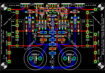
We have lots of caps and bypasses around the PSU and main board, which is not bad at all and one can use them or omit but in my opinion some are more important than others.
On the PSU the most important ones are those that bypass the zeners and here quality is more important than quantity.
For the zeners I would only use MKP’s some 0.47u or up to 1u and no need for the lytics. More so, I would prefer a 0.22u MKP instead of the lytic.
For the regulator output same thing, no lytic and a mylar or poyprop to give stability, 1u is enough, even less if you want.
You can omit the bypass on the main caps of the PSU more so if you use 4.7mf. but that is optional as we said.
Now on the main board a bypass on the supply caps (-+) will be welcomed.
As you can see I'm quite opinionated😀
We have lots of caps and bypasses around the PSU and main board, which is not bad at all and one can use them or omit but in my opinion some are more important than others.
On the PSU the most important ones are those that bypass the zeners and here quality is more important than quantity.
For the zeners I would only use MKP’s some 0.47u or up to 1u and no need for the lytics. More so, I would prefer a 0.22u MKP instead of the lytic.
For the regulator output same thing, no lytic and a mylar or poyprop to give stability, 1u is enough, even less if you want.
You can omit the bypass on the main caps of the PSU more so if you use 4.7mf. but that is optional as we said.
Now on the main board a bypass on the supply caps (-+) will be welcomed.
For the zener bypass caps I simply followed Nelson Pass' previous design work, although he did advise that I should use something low impedance/low inductance like the PanaFC's in that position.
On the regulator output caps, that was the subject of some research and discussion. Nelson advised, and my follow up research pointed in the same direction, that for best performance a significant quantity of capacitance is needed after the regulator, the rationale being that you want the time constant response of the post regulator capacitance to be below the lower frequency response limit of the amplification circuit. I seem to remember Nelson saying something to the effect, that if cost wasn't a consideration, to put as much capacitance after the regulator as you put in front of it.
Lastly, the regulation transistors become less effective at rejecting higher frequencies such as RFI, especially when driving a relatively high impedance following stage (the transistors own capacitances can start to come into play), so the film bypass caps on the main psu caps are present to shunt away RFI before the regulators. At least that was my rationale.
My two cents
That sounds quite good🙂 It would be nice to have this classic gem, as a reference for other preamps😎How about a Threshold NS10 pre?
Steen.
Thanks Terry!
I was hoping you would post something like that, as it aswered a couple of my questions.
I think I will probably leave the PS alone unless the there is a large outcry to change it. The PS is actually the easiest part to build without a PCB or with a home made PCB, so if people want to experiment with other power supplies it would be easy enough to do.
I will add pads for additional zeners just in case someone qnts to use this PS for other projects.
Cheers!
Russ
metalman said:
On the regulator output caps, that was the subject of some research and discussion. Nelson advised, and my follow up research pointed in the same direction, that for best performance a significant quantity of capacitance is needed after the regulator, the rationale being that you want the time constant response of the post regulator capacitance to be below the lower frequency response limit of the amplification circuit. I seem to remember Nelson saying something to the effect, that if cost wasn't a consideration, to put as much capacitance after the regulator as you put in front of it.
Capacitance right after the reg will form a Pi filter with the R and C present on the main board which in itself is not a bad idea. What calls my atention is the lack of bypass at the main board.
For anyone who is interested I started a thread for the NS10 here:
http://www.diyaudio.com/forums/showthread.php?s=&threadid=67915
Cheers!
Russ
http://www.diyaudio.com/forums/showthread.php?s=&threadid=67915
Cheers!
Russ

Isn't Q2 supposed to be a IRF9610? It says 610 on the board also.Here is the PS parts list:
Steen🙂
Everything looks very till now.
The boards are becoming a dream.
What kind of solution did you guys think of for the Heatsink?
For me its not so practical because the heatsinks cant be mounted anywhere. Wouldnt it be good to extend the PCB so we could mount the Heatsnink or Heatsinks on the PCB?
The boards are becoming a dream.
What kind of solution did you guys think of for the Heatsink?
For me its not so practical because the heatsinks cant be mounted anywhere. Wouldnt it be good to extend the PCB so we could mount the Heatsnink or Heatsinks on the PCB?
promitheus said:Everything looks very till now.
The boards are becoming a dream.
What kind of solution did you guys think of for the Heatsink?
For me its not so practical because the heatsinks cant be mounted anywhere. Wouldnt it be good to extend the PCB so we could mount the Heatsnink or Heatsinks on the PCB?
Actually I bleieve the board is very practical for HS, for a couple of reasons.
1) You really don't need a large HS at all, a simple flat piece of aluminum or a small 5" long extruded HS will do just fine.
2) You could actually mount the FETs/PCB directly to a case.
3) The idea of the layout is a common HS. It is a design goal. Extending the PCB would make it less practical to share a common HS.
The PCBs will come as soon as I get permission to produce them. I am sure Nelson is very busy. There is no rush.
Cheers!
Russ
- Home
- Amplifiers
- Pass Labs
- My Take on X-BOSOZ