Request for schematic
I was wondering if Terry or anyone else had a schematic for a suitable PS for this beast. 🙂 I was thinking Kari's looked good, but I can't find the schematic, and I don't want to muck it up.
If someone has one that would be great, otherwise, well I will improvise. 😀
Cheers!
Russ
I was wondering if Terry or anyone else had a schematic for a suitable PS for this beast. 🙂 I was thinking Kari's looked good, but I can't find the schematic, and I don't want to muck it up.
If someone has one that would be great, otherwise, well I will improvise. 😀
Cheers!
Russ
Hi Brian,
I actually mean 2 or 4 4700uf 100V total. But I would conside 4 x 2200 if that gets me more room for the rest of the PS. 🙂 Its going to be tight.
Cheers!
Russ
I actually mean 2 or 4 4700uf 100V total. But I would conside 4 x 2200 if that gets me more room for the rest of the PS. 🙂 Its going to be tight.
Cheers!
Russ
Russ,
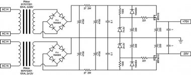
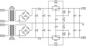
I've built two different power supplies for my preamp. The one I'm attaching here is the one I preferred overall, but the differences were pretty minor.
One note, the zener diodes indicated on the schematic represent a series stack of zeners adding up to the indicated values. It isn't necessary to hit those exact values, +/- a few tenths of a volt on either side are fine.
Also keep in mind that I was going for a full-on, no-holds barred approach to this powersupply. If space on the board is a problem, reduce the CRC pi filter down to a single capacitor per rail.
Attachments
One more quick question just so I get things straight.
Should I call the preamp a "X-BOSOZ" or a "CCS-X-BOSOZ" or something? What is the correct name? Just don't want the thing to look silly with the wrong name on it. 🙂
Thanks!
Cheers!
Russ
Should I call the preamp a "X-BOSOZ" or a "CCS-X-BOSOZ" or something? What is the correct name? Just don't want the thing to look silly with the wrong name on it. 🙂
Thanks!
Cheers!
Russ
One question answered
Looking at the power supply, it is clear why those coupling caps are needed. I thought the dual rails were at the same voltage.
Dummy question on power transformers. Guess the dual secondaries are used so that one side each is used per channel. So is it two dual secondary transformers or is it four?
George
Re: One question answered
Actually looks like its 3. You need 60VAC for the pos rail, so that's a single xformer (using both 30vac secondaries in series), 2 for stereo supplies. You need -15vac for the negative rail, so that's a single xformer (using a single secondary for each channel) for 2 stereo supplies.
Actually, the negative rails are reported at -9vdc as per kari's boards and these supplies give -20vdc. Never really understood the variation in negative supplies but there you have it.
Panelhead said:***
Dummy question on power transformers. Guess the dual secondaries are used so that one side each is used per channel. So is it two dual secondary transformers or is it four?
George
Actually looks like its 3. You need 60VAC for the pos rail, so that's a single xformer (using both 30vac secondaries in series), 2 for stereo supplies. You need -15vac for the negative rail, so that's a single xformer (using a single secondary for each channel) for 2 stereo supplies.
Actually, the negative rails are reported at -9vdc as per kari's boards and these supplies give -20vdc. Never really understood the variation in negative supplies but there you have it.
My Circuit is really based on Terry's, not Kari's circuit. So I will probably stick with the rails Terry has suggested, but I think there is a whole range of voltages that will work.
Cheers!
Russ
Cheers!
Russ
Russ - since you have the room, why not move the resistors in the Pi section a bit further away from the caps for better cooling and less cap heating?
If the regulator drops 15 volts, it disspates 1.2W per channel powered. so plan on lots of sinking
If the regulator drops 15 volts, it disspates 1.2W per channel powered. so plan on lots of sinking
Forgot to add, count me as interested since it doesn't look like I'll get the boards I ordered from Kari.
Hi Bob,
Thanks for the input. I am working on another take. I appreciate the interest.
Cheers!
Russ
Thanks for the input. I am working on another take. I appreciate the interest.
Cheers!
Russ
Hi Russ.
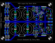
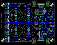
Consider making the tracks from C3+ and C4- as wide as possible.
(All the way to the terminal block at the outlet.)
If you go db-sided, you might be able to squeeze in some terminal blocks at the input. The only toplayertrack, would then be
one of the tracks going to the block for AC.
Otherwise it looks pretty.
Steen😎
Consider making the tracks from C3+ and C4- as wide as possible.
(All the way to the terminal block at the outlet.)
If you go db-sided, you might be able to squeeze in some terminal blocks at the input. The only toplayertrack, would then be
one of the tracks going to the block for AC.
Otherwise it looks pretty.
"X-CCS-BosoZ" taste the best to me🙂 Although you would miss the "CC" part that way...Should I call the preamp a "X-BOSOZ" or a "CCS-X-BOSOZ" or something?
Steen😎
Russ, I'm pretty sure you can enlarge the outline of the board to avoid having the heatsinks hanging off the board (which looks stupid IMHO) even with the free version of eagle. You just can't place any components outside the 3.15"x3.95" active area 🙂
/U.
/U.
Couldn't someone send that man a key to unlock that program😀
Otherwise we have to let the hat go round😉
You dont really need 100v caps on the negative rail, 35v would be enough. That could save some space.
Steen🙂
Otherwise we have to let the hat go round😉
You dont really need 100v caps on the negative rail, 35v would be enough. That could save some space.
Steen🙂
- Home
- Amplifiers
- Pass Labs
- My Take on X-BOSOZ