Hey Gooch,
Let me encourage you. I'm really enjoying it. Playing it through a Perrreaux 9000B right now. Really, really nice. It adds just a tad more kick than the B1 but still very true to the sound. I hope you get the bugs ironed out.
Blessings
Thanks Terry I think I will look at for my winter project I have to finish up a few other things first.
unbalanced to balanced
what i can not seem to find out is if the X-Bosoz is still able to function as a unbalanced to balanced converter.
can somebody please shed some light on this?
Mat.
what i can not seem to find out is if the X-Bosoz is still able to function as a unbalanced to balanced converter.
can somebody please shed some light on this?
Mat.
HI Guys,
I am to the point that I want to hook up all three channels and I started to install a switch and realized that I am probably going to need some kind of relay setup due to the balanced inputs. Can someone suggest a method for this? I don't want to reinvent the wheel if I don't have to.
Thanks, Terry
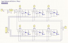
OK, no responses. I am thinking of using a 6 channel board like this one.
Source Input Selector 6CH Bare PCB 6 to 1 Way Stereo | eBay
I'm thinking I can use two relays per channel and sever the traces between channel 3 and 4 and add another block terminal. Does this sound like a good option? I looking for some help here.
Thanks, Terry
Source Input Selector 6CH Bare PCB 6 to 1 Way Stereo | eBay
I'm thinking I can use two relays per channel and sever the traces between channel 3 and 4 and add another block terminal. Does this sound like a good option? I looking for some help here.
Thanks, Terry
links to ebay are not working at DiyA , from some reason
use tiny-link extension for FF or something similar
however
take regular stereo relay based selector
say that you want 4 inputs ; that means 4 relays
if you need balanced , then just use one 4 relay board for one channel , taking + and - phases instead of stereo channels
then double it for second channel
Yeah, not sure how to fix the ebay link thing. It it the way this forum deals with links. Other forums I use don't have that problem.
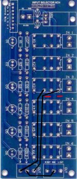
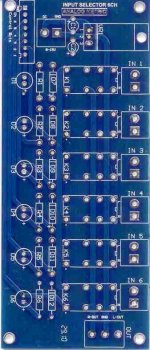
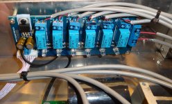
I am attaching a couple pics to show how I would like to do it. I would use channels 1&4 for + & - for channel one, then 2&5 for channel two and 3&6 for channel 3. I only need three channels. I would just couple the power for those pairs.
See any problems with this.
Thanks, Terry
I am attaching a couple pics to show how I would like to do it. I would use channels 1&4 for + & - for channel one, then 2&5 for channel two and 3&6 for channel 3. I only need three channels. I would just couple the power for those pairs.
See any problems with this.
Thanks, Terry
Attachments

Last edited:
Thanks Bob, that's what I'll do. Actually, I found that the same company that sells the PCB sells a kit for only $11 more. I don't think I can buy the components for $11.
Thanks again, Terry
Thanks again, Terry
Hi Terry,
it would be good to use a resistor (47k) from every input (+IN, -IN) to ground to avoid klicks, pops etc. when switching channels.
William
it would be good to use a resistor (47k) from every input (+IN, -IN) to ground to avoid klicks, pops etc. when switching channels.
William
Hi Guy,
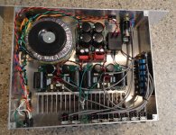
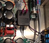
I just want to report in. I bought this kit from ebay and modified it the way I showed above. I found a 12Vdc 100mA wall wart to power it. I just hot glued the wall wart to the bottom of the case. Clean and simple. I now have three balanced stereo input channels. Very simple and clean. I have attached some pics for those who may be interested.
Blessings, Terry
Attachments
Hi Guys,
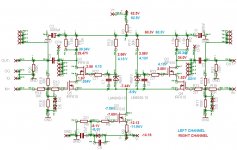
I finally got around to swapping that huge transformer for a couple small transformers. While testing it afterwards, I noticed that the right channel had lower output. So I started taking some measurements and the numbers around Qx didn't look right so I replaced it. That didn't help so I am posting a schematic with the voltages for both channels. Please take a look and see if you can see where it is broken.
Thanks, Terry
Attachments
Last edited:
R8 needs to be decreased for left channel , to get same voltage at Qx drain , in both channels
or , even better - look for same voltage at Q2, Q3 drains , in both channels
even if current difference is just 6.6mA , that's almost 10%
or , even better - look for same voltage at Q2, Q3 drains , in both channels
even if current difference is just 6.6mA , that's almost 10%
Last edited:
The left channel is the one that is working properly. Should I them increase R8 in right channel?
Thanks, Terry
Thanks, Terry
possible that way , too
how do you know which channel is working properly ?
I understood that gain is different , nothing else
however , I would increase cascode voltage , too ...... and include some amount of source degeneration for gain mosfets
say , at least 15 to 22R
how do you know which channel is working properly ?
I understood that gain is different , nothing else
however , I would increase cascode voltage , too ...... and include some amount of source degeneration for gain mosfets
say , at least 15 to 22R
The left channel sounds better. Right channel sounds whimpy. The left channel has even drain voltages side to side and the right channel they are 4.5V apart. I don't know how to increase cascode voltage and I don't know what source degeneration is.
Thanks, Terry
Thanks, Terry
- Home
- Amplifiers
- Pass Labs
- My Take on X-BOSOZ