Member
Joined 2002
Pathmark said:Thanks for clarification on R5 but I still have question about PS.
Why is 75V the correct value if my ps is only delivering 70V? It seems that the value of zener should not be higher than value you are trying to regulate. Therefore I was able to fix my issue by lowering the zener stack value to 60V. Is this logic incorrect?
Sorry if these questions are obvious to some but I may need a little more help than others!
PM
Nothing wrong with asking more questions, the more the better. It's always better to be sure than to let the smoke out 😀
jleaman said:Nothing wrong with asking more questions, the more the better.
True only when there are answers to the questions.

more newbie questions
So both PSU's working fine and one channel making music, only one-channel left!
My question is as follows: What are the possible reasons I have conductivity between 610's and my chassis?
I am using mica pads and nylon screws same as the other channel, but I seem to have 2 transistors which which have some connection to chassis. Where should I start looking?
Thanks,
Pathmark
First, physically seperate the 610's from the chassis (so you can see light between the two) and check conductivity again.
If that doesn't solve it, it could be a short to ground, either a solder bridge, dropped piece of lead clipping, or a dead fet. Check conductivity between the pins of each fet (they should always measure like a diode). If you find 0-ohms between any two pins, you have found the problem.
If that doesn't solve it, it could be a short to ground, either a solder bridge, dropped piece of lead clipping, or a dead fet. Check conductivity between the pins of each fet (they should always measure like a diode). If you find 0-ohms between any two pins, you have found the problem.
Once I had a short because there was a small grain of aluminium under one pad.
Brian, may I ask again about the bipolar electrolytic cap on the pre board?
I can't find it by my local supplier. May I use a smaller value poly cap? Or I could use two electrolytic caps with one leg in common to make a home made bipolar?
Brian, may I ask again about the bipolar electrolytic cap on the pre board?
I can't find it by my local supplier. May I use a smaller value poly cap? Or I could use two electrolytic caps with one leg in common to make a home made bipolar?
Member
Joined 2002
thomaseliot said:Once I had a short because there was a small grain of aluminium under one pad.
Brian, may I ask again about the bipolar electrolytic cap on the pre board?
I can't find it by my local supplier. May I use a smaller value poly cap? Or I could use two electrolytic caps with one leg in common to make a home made bipolar?
This is exactly why i use the ceramic pads now.
Great Memorial Day
So just wanted to say a big thanks to all you fellas who replied to my noob questions. I have about 10 hours of continuous play, both channels working, everything fixed in place and chassis completed.
In the end I had problems with zeners, mosfets, mica pads and despite my own skills I have a working xbosoz. Again thanks to all you guys who make this hobby/obsession possible!
Attachments

Excellent news! 🙂 I knew you would work It out. Congratulations to you!
Happy Memorial Day.

Cheers!
Russ
Happy Memorial Day.
Cheers!
Russ
Member
Joined 2002
Re: Great Memorial Day
mmmmmmmm, macbook 😛
Whre did you get the case ? Any more close up pictures ? Inside ?
Pathmark said:So just wanted to say a big thanks to all you fellas who replied to my noob questions. I have about 10 hours of continuous play, both channels working, everything fixed in place and chassis completed.
In the end I had problems with zeners, mosfets, mica pads and despite my own skills I have a working xbosoz. Again thanks to all you guys who make this hobby/obsession possible!
mmmmmmmm, macbook 😛
Whre did you get the case ? Any more close up pictures ? Inside ?
More pictures
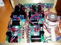
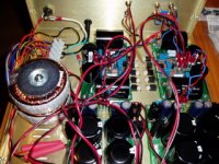
Hey jase here are some pictures of the inside. The case is a par-metal 12x10x4. I also used a glassware attenuator, hence the three knobs.
So a couple of "last" questions. Now that I have this thing working how can I be sure I am getting the correct operation. Are there a couple of critical values I should check?
Also the PSU's are getting pretty hot, actually it is mostly the + rail. The transformer is also pretty warm but the fet heatsinks are hot. Does this seem OK?
Pathmark
Attachments
Member
Joined 2002
Re: More pictures
Mine get warm too 🙂 the positive is the highest voltage, it will get warm.
Pathmark said:Hey jase here are some pictures of the inside. The case is a par-metal 12x10x4. I also used a glassware attenuator, hence the three knobs.
So a couple of "last" questions. Now that I have this thing working how can I be sure I am getting the correct operation. Are there a couple of critical values I should check?
Also the PSU's are getting pretty hot, actually it is mostly the + rail. The transformer is also pretty warm but the fet heatsinks are hot. Does this seem OK?
Pathmark
Mine get warm too 🙂 the positive is the highest voltage, it will get warm.
One channel down
Hey guys after doing some cosmetic work on the case one of channels is not working. As compared to the other channel I noticed much higher temp on 3W resistors r1/r6. I have take the following measurements but not sure what to do next.
Good channel
31.3 across r1
31.3 across r6
56.1 across r10
24.7 across r10/r1
24.7 across r10/r6
Bad channel
60.7 across r1
60.7 across r6
54.9 across r10
5.8 across r10/r1
5.8 across r10/r6
Any guidance would be much appreciated?
Pathmark
Any suggestions would help
Hi all,
Still trying to get one channel working. Measurements as mentioned above but not sure what may be the cause or check next.
any suggestions would be appreciated.
Pathmark
Hi all,
Still trying to get one channel working. Measurements as mentioned above but not sure what may be the cause or check next.
any suggestions would be appreciated.
Pathmark
PM-
Are your component values referring to the PS schematic you posted on the other thread? --nevermind, I see there is no R10 on that schematic.
It was a bit of effort to dig up the other thread to try to find the correct schematic you were referring to--and actually I didn't find it.
Maybe we could talk some nice moderators into moving the posts about your XBOSOZ off of Russ White's thread onto yours. I think you would get more help that way.....
Also, if you post the schematic or at least a clear link to the schematic, I think you will get a lot more replies. I have a bunch of notes from voltage measurements I took on my XBOSOZ, but I can't offer any insight without a schematic for your XBOSOZ.
JJ
babowana,
thanks for reply but i could not see details of attachment, can you re-post? thanks.
jj,
the schematic is post #1, the boards are twisted pear audio.
pathmark
thanks for reply but i could not see details of attachment, can you re-post? thanks.
jj,
the schematic is post #1, the boards are twisted pear audio.
pathmark
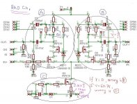
In your bad channel,
it apears as 60V across R1 (and R6).
It means 40mA bias thru R1 and thru R6--total 80mA.
Measure the voltage across R2 (or R7) on the other side, too.
If the measured is 60V, then, something wrong in CCS.
If the measured is 0V, then something wrong on this side.
To know whether CCS works correct,
measure voltage across the source resistor.
If the measued is appearing about 2.15V, then CCS
is working correct.
Good luck!
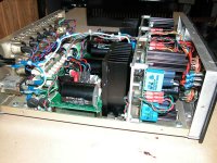
Well I had to practice getting 29 tomato's in a can before I stuffed my case, but I made it fit. Interestingly I thought I had blown fets on one channel. I had continuity from fet tabs to case. But when left idle for a wile and caps discharged they became open again. I was very careful with ESD protection and double checking and tested each section as Terry had outlined and was rewarded with a working unit. All my Pass projects the last thing I do before final assembly is install the fets. Russ, Brian looking forward to new controller.
Bill
Bill
Attachments
Member
Joined 2002
wirewiggler said:Well I had to practice getting 29 tomato's in a can before I stuffed my case, but I made it fit. Interestingly I thought I had blown fets on one channel. I had continuity from fet tabs to case. But when left idle for a wile and caps discharged they became open again. I was very careful with ESD protection and double checking and tested each section as Terry had outlined and was rewarded with a working unit. All my Pass projects the last thing I do before final assembly is install the fets. Russ, Brian looking forward to new controller.
Bill
Yup, that is a good definition of getting stuffed 😛
How long it take to get it all in there ?
- Home
- Amplifiers
- Pass Labs
- My Take on X-BOSOZ