PSU Question
Ok so I did not report the issue correctly.
The problem is only on the positive rail, but it is the same for both boards. I only see 4.5V and then smoke.
It seems that something (i.e. zener or diode) is not correct orientated but it matches board graphics and the negative rails works.
Please a little help.
Pathmark
Re: PSU Question
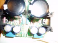
Its difficult to trouble shoot without being able to see and put a DMM to the PCB.
Can you post a picture?
Cheers!
Russ
Pathmark said:Ok so I did not report the issue correctly.
The problem is only on the positive rail, but it is the same for both boards. I only see 4.5V and then smoke.
It seems that something (i.e. zener or diode) is not correct orientated but it matches board graphics and the negative rails works.
Please a little help.
Pathmark
Its difficult to trouble shoot without being able to see and put a DMM to the PCB.
Can you post a picture?
Cheers!
Russ
Member
Joined 2002
Pathmark said:Russ,
Sure I can post, just let me know what is useful. If you have any advice of any measurements to take please let me know.
Pathmark
I can provide you with some really hi resolution photos of my psu if you wish.
Let me know.
Jase
jase,
thanks I have actually looked at the pictures on your website, but still not clear what is wrong.
As I see it the fault tree looks as follows:
* short-circuit
* incorrect orientation of diode, zener or cap
Unfortunately, not sure how I can tell, execpt visually for short. As I mentioned the only measurement I have is that I am only seeing 4.5V on the positive rail instead of 60+.
As for orientation,
(1) cap orientation, as you picture shows, all elect caps for positive rail should have negative terminal pointing to ground.
(2) remaining caps do not have orientation.
(3) Zeners (zd1) stack and diode (d16), seem to have opposite orientation. Meaning the cathode lines are in opposite directions on the boards.
Any thoughts?
When you see smoke, where is it coming from? Resistor, zener, or the IRF610 (Q1)?
The opposing cathode marks are okay and correct. The diodes need to be lined up sequentially, and changing direction on the board is the most space-effificient way to do it.
The opposing cathode marks are okay and correct. The diodes need to be lined up sequentially, and changing direction on the board is the most space-effificient way to do it.
Hard to isolate the smoke as I did not want to permanently damage, but it does not seem like Q1 and I am only using 1 zener (75v) in the stack with zero ohm jumpers filling the remaining slots.
What would be the condition for resistors to smoke? Is there any measurement I can take on the board to check expected values?
Pathmark
What would be the condition for resistors to smoke? Is there any measurement I can take on the board to check expected values?
Pathmark
If Q1 is dead (short), it would cause a large amount of current to flow through the resistor (heat + smoke).
With the power off (and caps depleted), measure the resistance between the pins of Q1. If any combo measures low (0-10 ohms), replace Q1. The FETs are very static sensitive, so could have been dead before you even soldered it in.
With the power off (and caps depleted), measure the resistance between the pins of Q1. If any combo measures low (0-10 ohms), replace Q1. The FETs are very static sensitive, so could have been dead before you even soldered it in.
I measured Q1 and was not completely sure so I replaced it. Powered up, saw 68V+ and 221ohm resistor melted down.
Any ideas?
Any ideas?
C1
Hi,
I can't find a radial electrolytic 22uF bi-polar for C1 here in Europe. May I use a lower value poly cap?
Thanks
joe said:What function has C1 and why does it has to be non polarized? I tried to find an answer in the thread but may be i missed it.
Thanks for your help.
Joe
Hi,
I can't find a radial electrolytic 22uF bi-polar for C1 here in Europe. May I use a lower value poly cap?
Thanks
Pathmark said:I measured Q1 and was not completely sure so I replaced it. Powered up, saw 68V+ and 221ohm resistor melted down.
Any ideas?
Here are some pictures posted by Brian, maybe useful to check components placement and diodes orientation 🙂
http://www.diyaudio.com/forums/showthread.php?postid=812595#post812595
http://www.diyaudio.com/forums/showthread.php?postid=813095#post813095
I measured Q1 and was not completely sure so I replaced it. Powered up, saw 68V+ and 221ohm resistor melted down.
The values are not called out on the diagram, but the 220 ohm resistor should be the one in series with the gate. The gate is supposed to have very high resistance -- meaning 220 ohm resistor could not melt down.
But since it did ... That points to either a short at the mosfet pins or a bad FET.
JJ
Latest info and question about R5
I just wanted to say thanks for all suggestions and post resolution. FET's were not a problem although changing them really stinks!
The problem seems to be with 75v zeners. I replaced the single zener with a stack (24 + 24 + 9). The reason I did so was because it did not make sense to me that the zener stack should exceed power supply rating. My trafo was only reading 70V, therefore 75V did not make sense and Pass schematic (bosoz) shows 60+ after regulation.
The only other cause I can think of is that original 75V zener was not correct from digikey although I doubt that.
Anyway just want to confirm if this makes sense?
One other question about R5, is 10K required over the 221 or is it recommended as a cure for some specific issue?
Oh yeah, one channel working last night!
Pathmark
Re: Latest info and question about R5
I still suspect your FET is bad, as the gate should be a high impedance. You should get virtually no voltage across the gate resistor... ever. Even if you had bad zeners....
As for the 10K R5, it is required.
The value of R5 originally was incorrectly indicated. It should be 6.8K - 12K. Anything in that range is fine.
Cheers!
Russ
Pathmark said:I just wanted to say thanks for all suggestions and post resolution. FET's were not a problem although changing them really stinks!
The problem seems to be with 75v zeners. I replaced the single zener with a stack (24 + 24 + 9). The reason I did so was because it did not make sense to me that the zener stack should exceed power supply rating. My trafo was only reading 70V, therefore 75V did not make sense and Pass schematic (bosoz) shows 60+ after regulation.
The only other cause I can think of is that original 75V zener was not correct from digikey although I doubt that.
Anyway just want to confirm if this makes sense?
One other question about R5, is 10K required over the 221 or is it recommended as a cure for some specific issue?
Oh yeah, one channel working last night!
Pathmark
I still suspect your FET is bad, as the gate should be a high impedance. You should get virtually no voltage across the gate resistor... ever. Even if you had bad zeners....
As for the 10K R5, it is required.
The value of R5 originally was incorrectly indicated. It should be 6.8K - 12K. Anything in that range is fine.
Cheers!
Russ
75V zener was the correct value for this circuit. Your 70V trafo (unloaded, loaded shoudl be closer to 60V), after rectification willl easily give you enough voltage for the drop across the zener and fet.
The value of R5 originally was incorrectly indicated. It should be 6.8K - 12K. Anything in that range is fine.
Russ -- are we talking about the same resistor -- R5 as shown on the diagram PM posted on the other thread? If so, I am curious as to why this would need to be any more 220ohms?
It sounds like you are talking about the resistors that sets the current through the zener stack, R4??
I am with Grommet regarding the fet being bad--if resistor R5 was 220ohms and melted down......
JJ
jupiterjune said:
Russ -- are we talking about the same resistor -- R5 as shown on the diagram PM posted on the other thread? If so, I am curious as to why this would need to be any more 220ohms?
It sounds like you are talking about the resistors that sets the current through the zener stack, R4??
I am with Grommet regarding the fet being bad--if resistor R5 was 220ohms and melted down......
JJ
No I was not talking about R5 on the PS PCB, I was talking about R5 on the preamp PCB. Both R5 and R6 (gate stoppers) on the PS should be 221 (or even lower if people want).
Thanks for clarification on R5 but I still have question about PS.
Why is 75V the correct value if my ps is only delivering 70V? It seems that the value of zener should not be higher than value you are trying to regulate. Therefore I was able to fix my issue by lowering the zener stack value to 60V. Is this logic incorrect?
Sorry if these questions are obvious to some but I may need a little more help than others!
PM
Pathmark said:Thanks for clarification on R5 but I still have question about PS.
Why is 75V the correct value if my ps is only delivering 70V? It seems that the value of zener should not be higher than value you are trying to regulate. Therefore I was able to fix my issue by lowering the zener stack value to 60V. Is this logic incorrect?
Sorry if these questions are obvious to some but I may need a little more help than others!
PM
No Worries.

Because you lose some voltage to the FET. 🙂
Pathmark said:Why is 75V the correct value if my ps is only delivering 70V? It seems that the value of zener should not be higher than value you are trying to regulate. Therefore I was able to fix my issue by lowering the zener stack value to 60V. Is this logic incorrect?
The series regulator should work as a voltage regulator. If the voltage is Vd after the pi-filter, Vd is the voltage to the drain of the regulator MOSFET. So, the gate voltage (zener referenced voltage) is to be less than Vd. Then, we get the finally regulated Vs about 4-5V lower than Vg.
Otherwise, the arrangement is totally wrong. Measure Vd, Vg, Vs and see!

- Home
- Amplifiers
- Pass Labs
- My Take on X-BOSOZ