http://www.diyaudio.com/forums/showthread.php?postid=786135#post786135
hehe-just few more tricks in tube playground
coincidence-another shunt supply......
hehe-just few more tricks in tube playground
coincidence-another shunt supply......
If I can help you, send me a mail, Choky🙂I didn' even finished my BOZ .....
Steen.😎
steenoe said:Choky, do you mean it would sound better with even more volts on the trafo's secondaries? I have 2x25 before rectification at this point! I have a 2x30v trafo also, if that should be better? But thats a 160VA, so its a bit biggerabout heatsinking the BD's then? Okay, here is the last pic for today😀
check difference in last psu pic-for same current you have almost halved series resistors...... ripple rejection must be worse,in any case ;
stored (or-if you wish-braked energy) is smaller.
dunno it will sound better

in any case-you can try with 160VA iron OUTSIDE of box;
nobody tell ya what breadbording is ?
you always must have finished and good looking prototype?
who cares for heatsinkin' 😉
I see on pics that is allready good'nuff
regarding finishing my BOZ-you can't give me your spare time...

I know breadboarding allright😀 😀 Not a bad word about it🙂 I even did some myself😎 (your shunt reg for one;-))nobody tell ya what breadbording is ?
Nope, but I do like to anyways😀you always must have finished and good looking prototype?
I am still impressed by this shunt reg😀 😀 It just sounds so darn good🙂 Been listening all evening and I just want to keep on🙂 I can praise the NS10 to death, but still.... it simple just sounds great😎 I am glad I made it😉 With the shunt reg supply, its just wonderfull

Steen😎
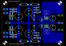
steenoe said:When we have this psu perfected, I hope Russ'ie-boy will make a lill nice pcb for it😀
I couldn't wait. 🙂
How is this?
Attachments

just one addendum :
put some " around Choky (hehe- like "Choky" )
we all know that reg is from some Ozy web page 😉
put some " around Choky (hehe- like "Choky" )
we all know that reg is from some Ozy web page 😉
next one will be retakin' psu part of my BOZ (at my www) in shunt type;
steeeens dream -shunt reg with IRFs 😱
steeeens dream -shunt reg with IRFs 😱
steenoe said:I finished the second edition of this preamp. It surprise me how good it sounds. It has a very crisp and clear sound, yet very, very pleasant to listen to. Not excactly what you are used to with these small transistor linestages. Parts used are Panasonic FC's for electrolytics, all filmcaps are Rifa PHE426 except for the output cap which is a 22uF MKP-roll, its the big black thing hovering over the boards. The feedback B2B cap is bypassed with a 470nF Rifa. Transistors are MPSA18 and the pnp device is a BC560C. Resistors if you care are BC metalfilm's. The psu is a 50VA 2x25v potted donut, connected to Choky's "shunt reg" supply.
Its described a bit earlier in this thread. I used small schottky's for the rectifier and good quality electrolytics for the smoothing. With the better parts and a better supply, its like the curtain went up🙂 This little preamp actually sounds very good. I won't rebuild this one right away; it stays in the main system for a while.
(Except for a slight trace of buzz that I have to hunt down. I can hear it when I stick my ear to the speaker)
To Choky: (and others who find it useful, ofcourse)
Current draw is 10ma on both the pos rail and the neg rail, so the current draw per channel is 20ma, as suggested earlier.
Here is, as usual, a piccy, of that little wonder.
Hope some of you find this information useful🙂
Steen😎
steen-
you can do better in two ways:
1.put that silly 😉 selector near RCAs on back,and use some extending shaft to it ,or
2. use shielded cables with SOLID iner conductor ,with opened shield at end end and grounded on start end.... I recommend that even in case of 1.
in case of 2. you preserve 90% of tiny solid core school goods ,but you have also all goods from shielding ( decreased hum and crosstalk)
off course,even volume can go to back-where it belongs
'xcuse me if I talking here about boiled water
now-goin' to sleep ............
😱
Russ White said:So did I at least come close? 🙂
Very nice Russ.😎
I would suggest, if I may, very short leads for the bypass at the rail trace and anode of diode and PLEASE add the posibility of a MKP type cap on same position.
Great Russ🙂 Thanks a lot😎How is this?
You are very kind, giving us those nice pcb layuots😉 I am allready itching to etch a couple😀
Thanks for the suggestions, Choky. I will try and do as you suggest, when I make the "Final" Megaclone. This little circuit is worth every effort to give it perfect working conditions🙂 I see now, why others are so happy about that NS10.you can do better in two ways:
Steen🙂
apassgear said:
Very nice Russ.😎
I would suggest, if I may, very short leads for the bypass at the rail trace and anode of diode and PLEASE add the posibility of a MKP type cap on same position.
Hi Tony,
Thanks for the suggestions! 🙂
Let me make sure I understand your ideas.
1) Optimize rail traces to bring them closer to the caps.
2) add MKP (I suppose 10 and 15mm spots are ok) bypass in additon to the electrolytics, but here I am not sure at which positions you mean. Could you please specify parts numbers.
Here is another general question.
Would it be better to use vertical TO220 package for the BDs. I imagine that is more flexible for heatsinking.
Also should I add more spots for optional zeners to make this a more flexible supply, say for assymetrical use like for Twisted XBOSOZ. 😀 Or.... Is that even possible or wise.

I hope to have PDFs for you guys very soon.
Cheers!
Russ
Steen,
..and anyone else that has has gone as far as steen has...
What would you suggest for a first build of a pre... a Bosoz or a NS10? I am looking for a better 'guarantee' of success so interest continues to the next project. These things take me forever so picking the right ones are important!
Thanks🙂
Russ, all of your suggestion are quite good.🙂 🙂 🙂
Yes, more flexibility will be a plus for any PSU design. Since this design is appropriate for preamps, as you suggest living space for a TO220 is enough, in an upright position with space for heatsinking similar to what Steen did on his prototype.
I would add space for 4 zeners to have adjusting voltage freedom. Just beside the zeners (short traces) add space for a small lytic (2.5 mm leads) and space for a film bypass with 15 mm leads (at least that is what I would use). This way anybody can decide if he want to use both caps or any single.
Size of the two sets of smoothing lytics seems ok for the 1,000u Choky suggested for the Pi filter (they could go closer though for 50V rating). Position of the resistors for these lytics is also nice since we have the flexibility to replace them with choke leads.
Now, for connections to the board, input and output, I would prefer screw type terminals from my point of view.😎
mpmarino said:Steen,
..and anyone else that has has gone as far as steen has...
What would you suggest for a first build of a pre... a Bosoz or a NS10? I am looking for a better 'guarantee' of success so interest continues to the next project. These things take me forever so picking the right ones are important!
Thanks🙂
One thing you must take in consideration is that NS10 is only a single ended pre. Bosoz can be used single or balanced at both ends.
🙂
Thats pretty good ideas. It could be fun, trying the shunt reg on a a BosoZ. If you would do so, you need 100v electrolytics, at least on the pos. rail, so you would need to make room for that on the board. As for the supply connections, I like screwterminals best, just like Tony🙂Would it be better to use vertical TO220 package for the BDs. I imagine that is more flexible for heatsinking.
A BosoZ is a safe bet, especially if its the X-CCS-CC version like the "Twisted one". Its much better as a balanced/unbalanced converter than the standard BosoZ. You cant really go wrong with that preamp🙂 Even if you dont need the Balanced signal handling at this point, you might need it later on😉What would you suggest for a first build of a pre
Steen🙂
The buzz I was complaining about is definately comming from the supply. I soldered some caps in across the diodes in the supply, but it didnt really take care of it. In the end I put in the lm317/337 supply I was using to start with, just to be sure. The Buzz disappeared, but that supply doesnt sound as good as the shunt reg. (except for the buzz ) Someone mentioned earlier that this circuit needs a very clean supply if powered by a dual rail supply. If I didnt make a mistake somewhere in the shunt reg I made, it needs to be cleaned up. Would it be possible to add a capacitance multiplier at the output end, without destroying the sound? Or something else?
Steen🙂
) Someone mentioned earlier that this circuit needs a very clean supply if powered by a dual rail supply. If I didnt make a mistake somewhere in the shunt reg I made, it needs to be cleaned up. Would it be possible to add a capacitance multiplier at the output end, without destroying the sound? Or something else?Steen🙂
steenoe said:The buzz I was complaining about is definately comming from the supply. I soldered some caps in across the diodes in the supply, but it didnt really take care of it. In the end I put in the lm317/337 supply I was using to start with, just to be sure. The Buzz disappeared, but that supply doesnt sound as good as the shunt reg. (except for the buzz
Steen🙂
1.try xformer with more volts -use 120 E resistors
2.try darlingtons instead BDs
3.try LM based CCSes in front of shunt regs
choky said:
1.try xformer with more volts -use 120 E resistors
2.try darlingtons instead BDs
3.try LM based CCSes in front of shunt regs
but-before all that,try to increase last cap at 2200uF or even 4700
hehe-I just remember that I use years ago 120.000uF as last cap in zener stab in Quad 33-out of box,naturally 😉
sound was soooooo smooth and natural,even if not overly detailed;
hehe-and it worked 4-5 minutes after unplugging from wall
- Status
- Not open for further replies.
- Home
- Amplifiers
- Pass Labs
- My Take on Threshold NS10