@HifiNut
Did you try only the 100uF/ZA? So without the MKP? How is performance then?
Thanks!
I have not tried 100uF ZA only. I guess that as long as the circuit is stable, it should sound fine. But whether it has the refinement of the MKP, I don't know. I guess the cap at this location is less sensitive comparing to the Vref cap.
The good thing about it is that, mixing 2.2uF MKP with 100uF ZA does not sound bad in this particular case. I usually don't like bypassing electrolytic caps, in most cases, the sound becomes worse, like two different sounds coming out from the speakers.
By the way, before Ikoflexer gives a reply what value of an electrolytic is good so that not to reduce gain too much, I am only doing the guessing here.
According to Ikoflexer, a larger value reduces the noise. But of course, it will be up to a point before things are screwed up, like 470uF makes it sound worse.
I have not tried 100uF ZA only.
In my experience the ZA "sounds" very good...... in my NAD-amplifier it bettered even the film coupling caps I used at that place by far. Enhanced transparency and smoothness, sound became more "real".
So I am very curious.
has the turn on time improved yet?I would find such a slow turn-on time unacceptable too.
The very slow first turn on may have been due to leakage of the "off the shelf" electrolytic.
Either the electrolytic must be reformed to it's rated voltage or the test must be repeated over a sufficient time scale to allow in circuit reforming.
A first test like that is useless information.
Andrew,
Your point may well be valid. If we use more scientific way of doing it, i.e. for the Idss 9mA / 3 = 3mA, how long does it take to fill up a 470uF capacitor to 12V?
Regards,
Bill
Your point may well be valid. If we use more scientific way of doing it, i.e. for the Idss 9mA / 3 = 3mA, how long does it take to fill up a 470uF capacitor to 12V?
Regards,
Bill
In my experience the ZA "sounds" very good...... in my NAD-amplifier it bettered even the film coupling caps I used at that place by far. Enhanced transparency and smoothness, sound became more "real".
So I am very curious.
I did not have the patience to wait until the 220uF ZA Vref cap to fully run in (I am now talking about Vref cap instead of output cap). After a hour or so, I found the 1.1uF MKP || 220uF ZA sounded muddy comparing to only the 1.1uF MKP, so I removed it. I am waiting for Ikoflexer to post the impedance plots to decide what values to use there.
In my experience the ZA "sounds" very good...... in my NAD-amplifier it bettered even the film coupling caps I used at that place by far. Enhanced transparency and smoothness, sound became more "real".
So I am very curious.
Did the film cap and the ZA have the same value? What place in the circuit? I guess there are many factors that can contribute to the sound.
For example, if you put a ZA at the output of a LM317/337, you would be looking for trouble. A garden variety electrolytic cap would sound 100 times better than the ZA there.
Last edited:
I usually don't like bypassing electrolytic caps, in most cases, the sound becomes worse, like two different sounds coming out from the speakers.
Bypassing of electrolytic caps is indeed very tricky.....
1Farad rising at 1Volt per second uses 1Ampere of current.If we use more scientific way of doing it, i.e. for the Idss 9mA / 3 = 3mA, how long does it take to fill up a 470uF capacitor to 12V?
That's where the Farad definition comes from.
If you have one millionth of a Farad (1uF) then that will rise at 1volt/second if you supply it with 1millionth of an ampere (1uA).
But that is not the problem.
If you supply 3mA when the cap is fully discharged and the leakage is varying from 3mA initially to maybe 30uA by the time 12hours have passed, then I think you can see that leakage will completely alter any calculations/predictions you may make. You must reform the capacitor before testing how long the circuit takes to charge up.
I'll go further.
You must reform all electrolytic capacitors to their rated voltage before listening to the circuit and/or measuring it's performance.
Last edited:
Thanks. How long does it take to reform? I know some people say a couple of hours and some say 3 months. Any more scientific studies on how long it takes?
I have not used a pen or calculator to do the maths but using that formula it would still take less than 1 second to fill up the 470uF to 12V, provided that there is no leakage.
I have not used a pen or calculator to do the maths but using that formula it would still take less than 1 second to fill up the 470uF to 12V, provided that there is no leakage.
Last edited:
Wow, that's a lot about capacitors. Yes, Bill, Salas, I was referring only to the value of the output cap, not the particular quality/manufacturer. As for the value vs noise vs output impedance, it depends so much on the layout of the output that it's pretty academic of a discussion.
Andrew, the turn-on time is not something that needs to be fixed. The J201 acts as a current limit of about 240uA and the larger the capacitor below it, the longer it will take to get up to Vout. I've used a 47uF there, and the turn-on time was acceptable. 1000uF would not be, for me.
Andrew, the turn-on time is not something that needs to be fixed. The J201 acts as a current limit of about 240uA and the larger the capacitor below it, the longer it will take to get up to Vout. I've used a 47uF there, and the turn-on time was acceptable. 1000uF would not be, for me.
test it.How long does it take to reform?
Apply 16Vdc through 100k resistor and measure how the resistor voltage varies with time. The resistor voltage is a rough indication of the cap leakage+charging current.
Once charging is substantially over the remaioining current is predominantly leakage +-a little bit of chage/discharge current depending on the stability of the supply.
The apparent leakage is very much affected by the DC supply voltage. A good regulated DC supply that is held at constant temperature will help a lot.
You may find that 6hours at 100k gets to within 105% of the ultimate leakage current. But tell us what you find.
You can reform a bank of caps using one resistor to feed each capacitor.
Measure across each resistor to see how similar or different the caps are.
Last edited:
Iko, I am not saying that turn on time needs any fix.The price to pay for adding more capacitance is the much longer time it takes to reach the desired rail voltage after turn-on. The voltage was set to 12V, it took a good 10 minutes to reach 11V. With 1.1uF, it took no time.
I am explaining to Hifi, why his apparent turn on time experiment is flawed.
There is nothing wrong with the circuit or it's performance.
It's the use of degraded electrolytics that has caused the problem, but once the chemistry is understood the problem goes away. It just needs time, either reform beforehand or give it time to reform in circuit. Don't blame the circuit when you don't understand how you have forced it to behave.
Bill, here the Vref bypass cap is stepped as follows: 1uF, 2.2uF, 4.7uF, 47uF, 100uF, 220uF, 330uF. The green solid line is 1uF, blue 2.2uF, red 4.7uF, ...
This low output impedance, again, has to be qualified. It is only in the perfect world of simulation.
This low output impedance, again, has to be qualified. It is only in the perfect world of simulation.
Attachments
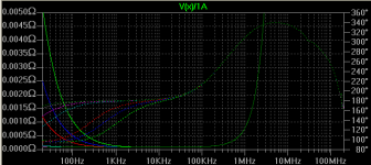
Bill, here the Vref bypass cap is stepped as follows: 1uF, 2.2uF, 4.7uF, 47uF, 100uF, 220uF, 330uF. The green solid line is 1uF, blue 2.2uF, red 4.7uF, ...
This low output impedance, again, has to be qualified. It is only in the perfect world of simulation.
Come on!
 I thought there was much to worry about but there is nothing. You are a perfectionist (like me
  ). The impedance even with 1uF at 20Hz is a plenty lower than most other regulators. I think value above 4.7uF is for deminishing return, wire resistance starts to dominate. I would not put an electrolytic there at all. No wonder I can't find anything wrong with my 1.1uF.
Another three factors here too: 1) most circuits have a much higher PSSR at lower frequencies, only above 500Hz they start getting into trouble; 2) Human hearing is less sensitive outside the 1kHz - 8kHz region; 3) Below 150Hz the room and loudspeaker interaction dominates the distortions.
I will be happily live with my 1.1uF or 2 x 1.1uF

I am not sure but I don't think the phase shifts of the smaller caps would have any sonic effects. I also guess that the intension of getting the impedance flat down to 20Hz is that, ripples at 20Hz may affect the sonic at higher frequencies, because, ripples are, ripples. I don't have these issues with my active XO because frequency regions are all nicely divided up.
Last edited:
You are right, of course. I was not referring to cap quality, but cap value uF.
Tried 2.2uF MKP || 6 x 2.2uF MKT and did not like it. Better 2.2uF MKP || 100uF electrolytic.
Interesting..... I wonder if this combo can work nicely on the DCB1 and S.S.S.Reg v1.2 too. 😕
It can get 100uF electrolytic instead of the output Zobel too. I.e you just have to delete the resistor that was making the low value film output cap termination ''leaky'', and swap the film cap or parallel it. In DCB1 I use 100uF as termination for instance. It will cut gain as it goes higher, and will make the phase different. With an electrolytic you never know what will be with age or heat or real specs OTOH. The ''leaky'' film cap Zobel thing will be steady. Then again just 100uF lytic is smaller for layout and it may suite particular loads subjectively. YMMV.
Bypassing of electrolytic caps is indeed very tricky.....
Is that applicable to both coupling and decoupling application as well? As far as I know, it does affect coupling application but not decoupling.
Is that applicable to both coupling and decoupling application as well?
Both.
But I am not the expert here, sources are found here on DIYAUDIO.
Has to do with oscillations and microphonics (movement of film material) as I understood it.
- Status
- Not open for further replies.
- Home
- Amplifiers
- Power Supplies
- My take on a discrete shunt voltage regulator